119
A 15K shunt resistor and a 7.5K series resistor are required closed to
the contact in field side. Refer to the following block diagram of this
channel configuration, and a field wiring example.
ATTENTION:
For Channels that are configured with a debounce, the UIO will
declare that the channel has changed state if all the
consecutive samples are in the new state for the configured
debounce time period.
Field wiring for Digital Output
When UIO is configured as a Digital Output, the channel can supply
up to 0.5A to the field. See the following table for the specification of
DO.
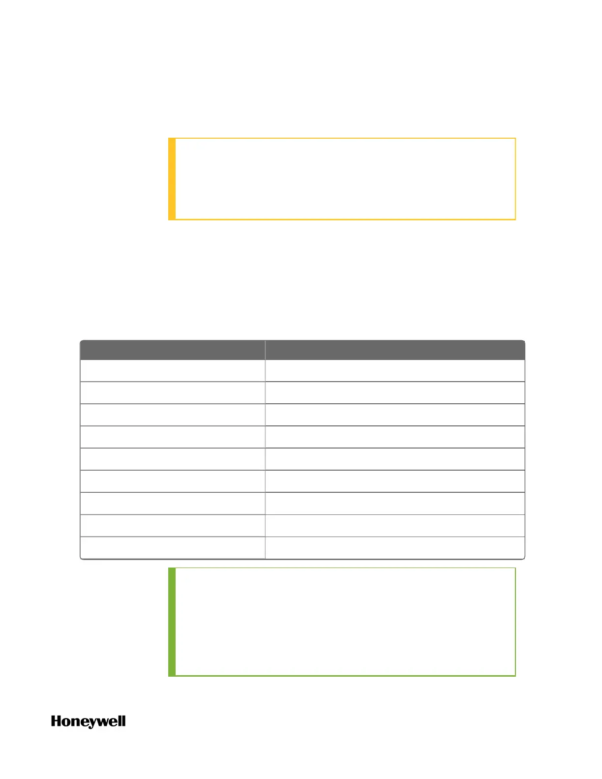
Table 5-18: UIO Specification for DO
Item Description
Open wire detection Configurable
Short circuit detection Enabled by default and un-configurable
Maximum (resistive Load) 500mA
Minimum Load 20mA with OWD and 0mA without OWD
Maximum load capacitance 1 uF
Voltage Drop < 1 V (at 500mA)
Off Current < 0.1mA
Lead breakage test current Approx. 10 mA
Output Current 0 - 23 mA
TIP:
If a Universal I/O Channel configured as Digital Output reports
an “OP Fail in circuit/field wire” alarm, the most likely cause of
the alarm is a broken wire. The user should check the continuity
of field wiring. It is suggested to enable Line Monitoring for
DOs so that the Event Log can clearly identify the problem as a
possible wire break.
 Loading...