Appendix A - Installing RTP
ATTENTION:
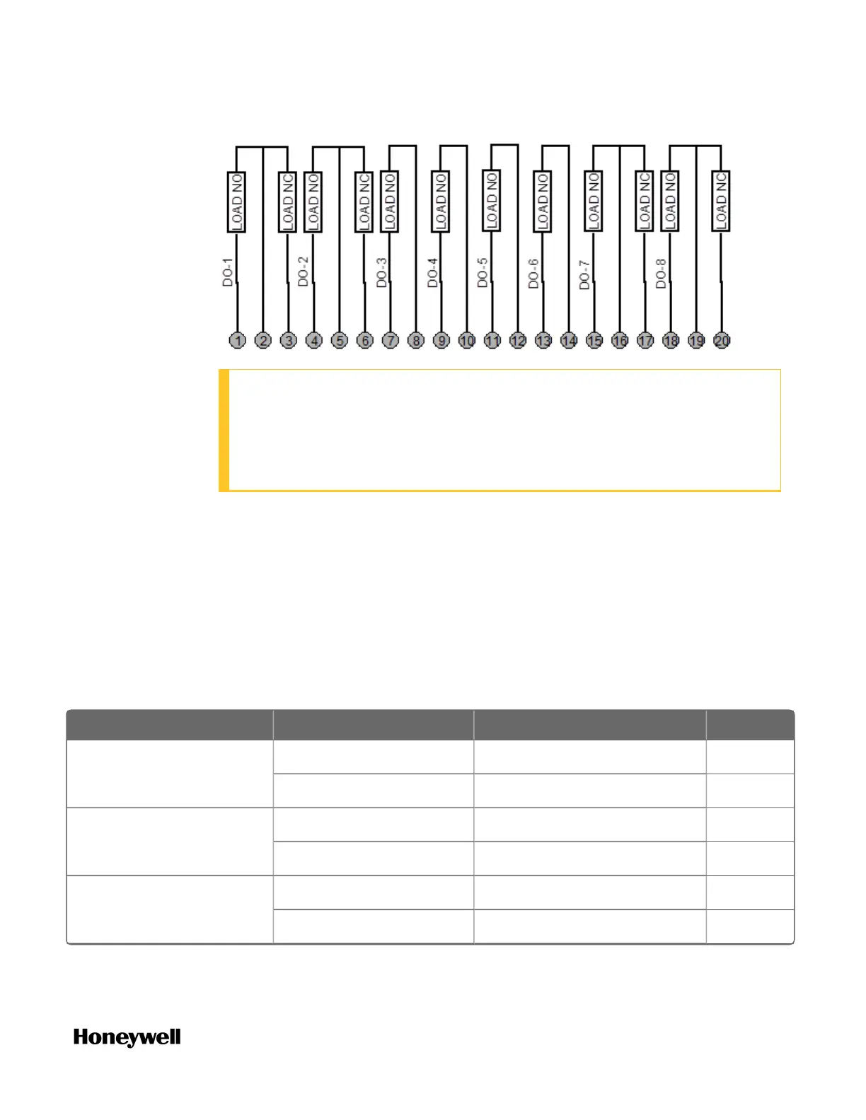
l As shown in the schematic, each switch is SPST and opens and closes
one lead of the relay wiring. If your application requires opening and
closing both sides of the load wiring, then an external DPST switch is
required.
RTP Cable wire positions, colors, and internal schematic
RTP Cable wire positions and colors(Applies to UIO, 4 AO, 16
DI and 8 DO)
See the table below for RTP Cable wire positions and colors (Applies to UIO, 16 DI
and 8 DO) :
Twisted Pair Number Module TB Position RTP J1 Plug Connector Color
1 1 6 Black
2 7 Red
2 4 9 Black
5 10 White
3 6 20 Black
7 19 Green
Table A-3: TP Cable wire positions and colors (Applies to UIO, 4 AO, 16 DI and 8 DO)
219
 Loading...