Control Processor Module
A Redundant Controller Rack contains two CPMs. Either CPM can be
primary.
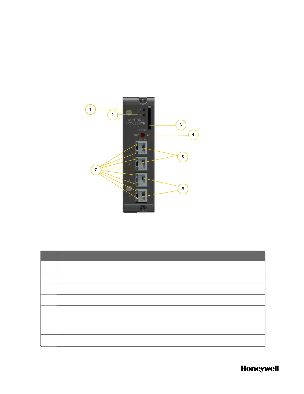
The CPM is shown in the following figure.
Figure 4-1: Control Processor Module
As indicated in this figure, CPM includes:
Table 4-2: Control Processor Module Components
Item Description
1 Status LED indicator for the CPM.
2 Role LED indicator for the CPM.
3 SD card slot: Reserved for future use.
4 Mode switch
5 Ethernet port 1 (ETH1) and Ethernet port 2 (ETH2) for uplink connectivity to
an Experion FTE network. ETH1 should be connected to the FTE A (yellow) and
ETH2 should be connected to FTE B (green) networks. For more information,
see Experion documentation.
6 Ethernet port 3 (ETH3) and Ethernet port 4 (ETH4) for connectivity to the
44
 Loading...