Each slot in a rack includes a set of guides that locate the circuit
board in the rack, and a pin socket in the backplane that receives the
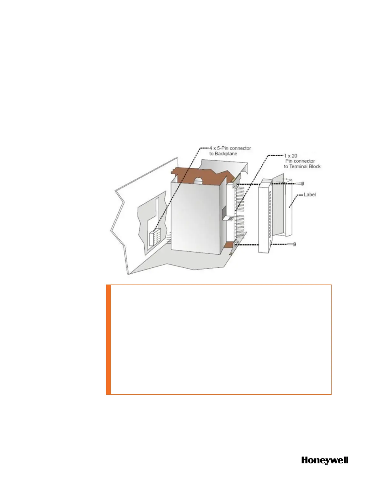
associated pin plug at the back of the I/O module.
At the front of each I/O module, a pin plug receives the associated
socket on the back of a terminal block. When the I/O module is
inserted into the rack and the terminal block is placed on the circuit
board, two captured screws in the terminal block are fastened to
metal tabs on the rack.
Figure 5-14: I/O module installation
CAUTION:
l Do not use an input/output terminal block if the terminal block
is damaged, if the door is missing, or if one or both mounting
screws are missing.
l Always tighten both terminal block screws to proper torque
settings before applying field power to the module. Torque to
0.4 - 0.5 Nm (3.5 - 4.4 Lb-In).
l Do not apply energized (“live”) field wiring to an input/output
module that is not installed in one of the racks in the system.
l Do not operate the module without a Protective Earth
connection on the rack.
Failure to comply with these instructions could result in death or
serious injury.
88
 Loading...