Appendix A - Installing RTP
b. Connect the appropriate cable to the module at ControlEdge 900
Controller. Possible options are:
l 900RTC-H1210 Remote Termination Low Voltage Cable Assembly, 1.0
meters long
l 900RTC-H1225 Remote Termination Low Voltage Cable Assembly, 2.5
meters long
l 900RTC-H1250 Remote Termination Low Voltage Cable Assembly, 5.0
meters long
c. Install the module label onto the module connector cover.
d. Connect shield drain wire to the grounding bars at the base of the
ControlEdge 900 Controller rack. All field-wiring shields must be grounded
as described in the shield grounding section.
2. Mount the RTP to the DIN rail.
a. Secure the RTP to the rail. See "Securing the RTP to the DIN rail" on
page228 for more information. for details.
b. Connect the cable to the RTP.
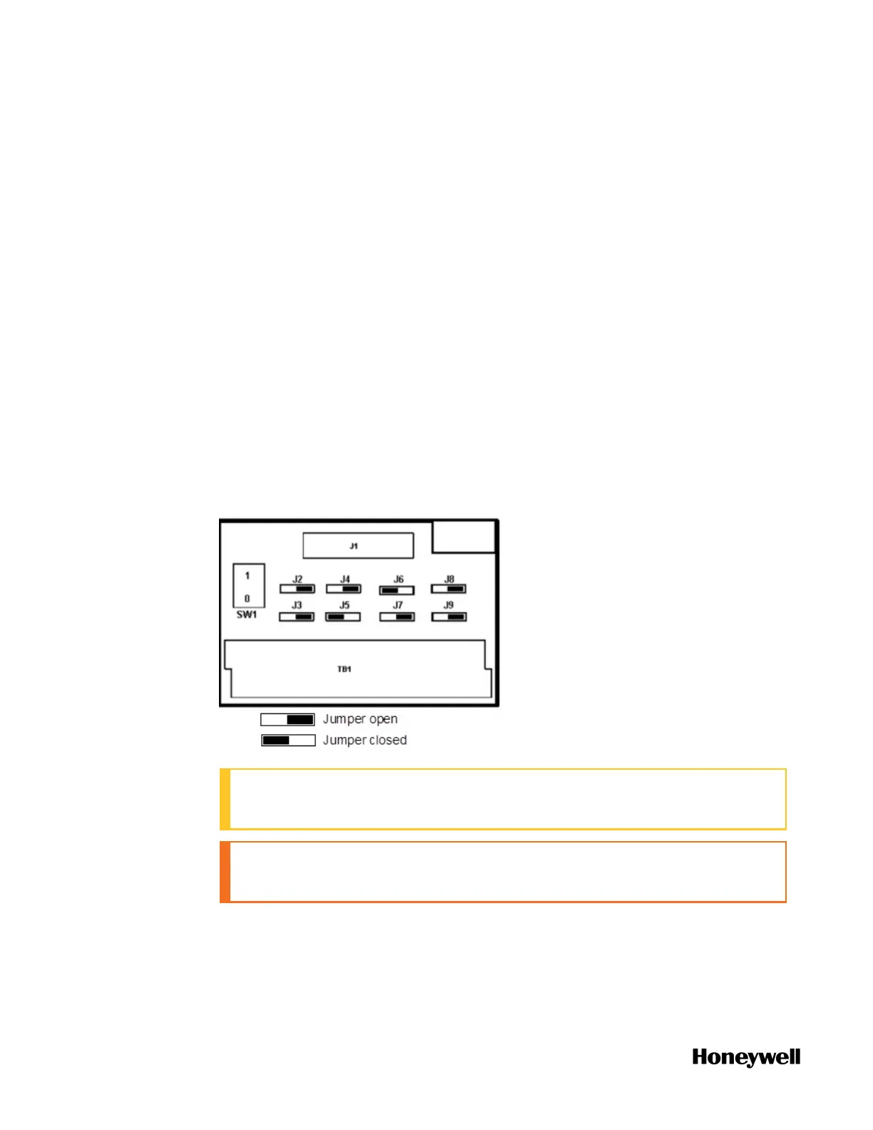
3. Set jumper positions as shown below for use with an analog output module.
ATTENTION: SW1 is not used. Module Removal and Insertion Under
Power is not affected by using the RTP.
CAUTION: Explosion hazard. RIUP is not supported in Division 2/ Zone
2.
See "RTP Cable wire positions, colors, and internal schematic" on page219 for
more information.
190
 Loading...