Appendix A - Installing RTP
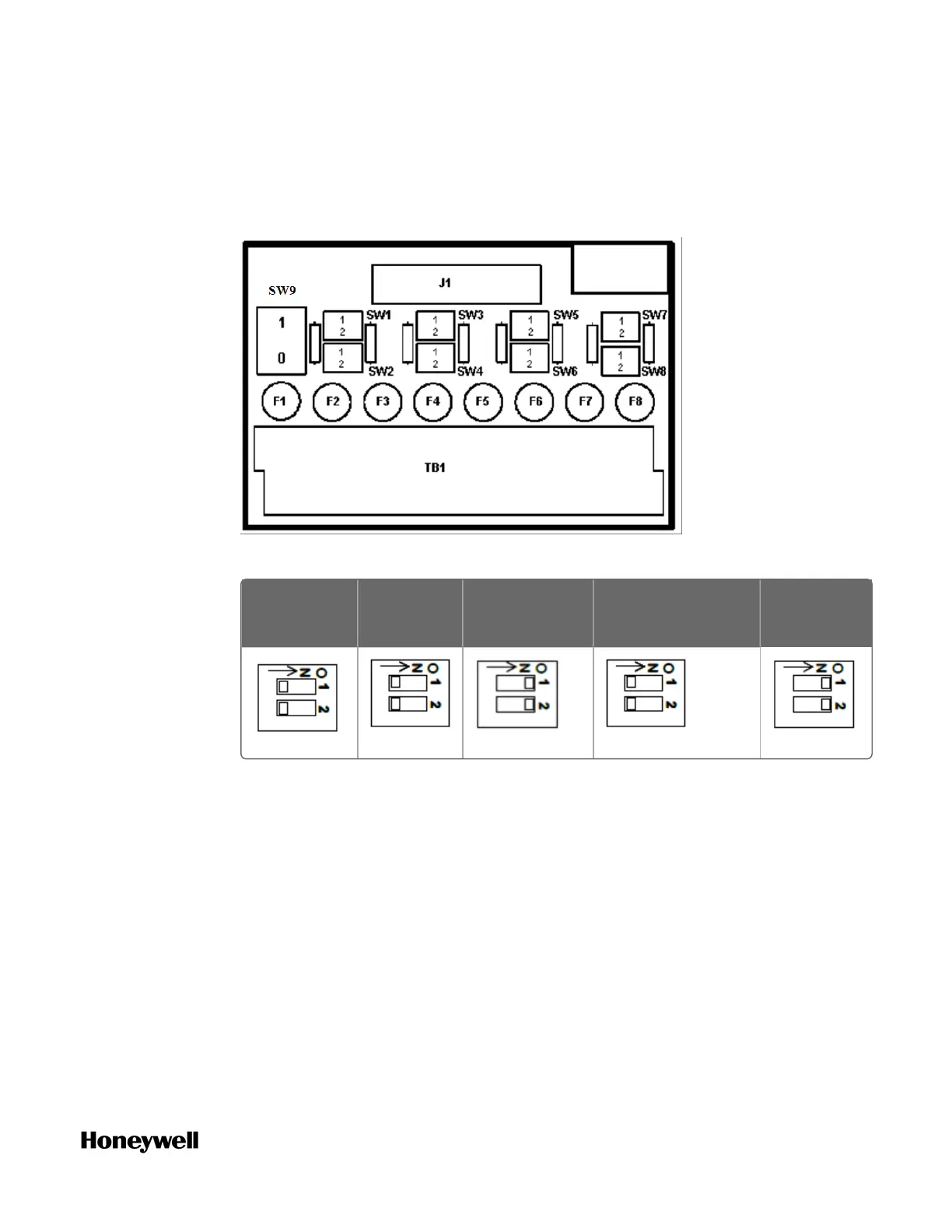
3. Set DIP siwtch position SW1 through SW8.
Set each input’s DIP switch positions according to the input type. For Input n
use Switch n. For example, for Input 1 use Switch 1, for Input 2 use Switch 2,
etc. If an input is not used, set its DIP switch positions to OFF.
Fuses: 80mA
Volt, millivolt Ohms
Transmitter:
Loop Powered
Milliamp:
Externally Powered
RTD:
Transimitter
SW9 is the red power switch for 24 volt supply. Module RIUP is not affected by
using the RTP.
See "RTP Cable wire positions, colors, and internal schematic" on page1 for
more information.
4. Connect field wiring, as shown below.
Refer to the following figures for field wiring. Any input type can be wired to
any of the 8 inputs. After wiring, double-check DIP switches settings for each
input type (Step 3).
Figure A-3: Analog input terminals
193
 Loading...