Appendix A - Installing RTP
d. Connect both shield drain wires to the grounding bars at the base of the
ControlEdge 900 Controller rack. All field-wiring shields must be grounded
as described in the shield grounding section.
2. Mount the RTP to the DIN rail.
a. Secure the RTP to the rail. See "Securing the RTP to the DIN rail" on
page228 for more information. for details.
b. Connect the cable to the RTP.Cables are marked “RTP A” and “RTP B.” In
step 4, RTP A will be wired to outputs 1-16, RTP B to outputs 17-32. You
can write on the RTPs’ labels to distinguish them.
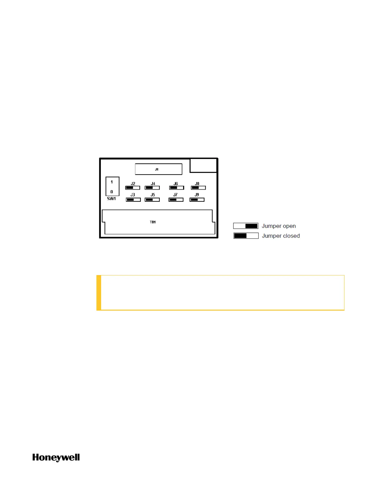
3. Set/verify jumper positions on each RTP as shown.
Module Removal / Insertion Under Power (RIUP) is supported by turning off
Switch SW1 to allow removal of the module from the rack without causing an
arc.
ATTENTION: SW1 opens current loop on the ground side so that RIUP of
module is possible, but voltage is still present on the positive side at RTP
and module terminals.
See "RTP Cable wire positions, colors, and internal schematic" on page1 for
more information.
4. Connect field wiring.
211
 Loading...