83
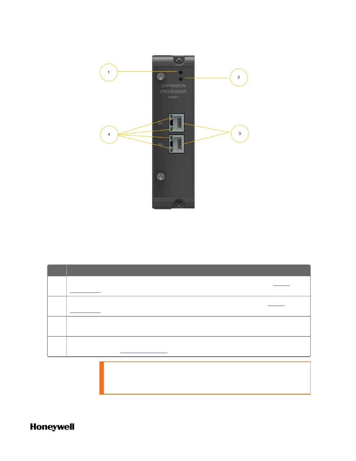
It is installed in the expansion I/O rack and provides the link between
the CPM and remote I/O modules. Features at the front of the module
include:
Table 5-9: Expansion Processor Module Components
Item Description
1 Status LED indicator for EPM functions. For more information, see EPM
Indicators section.
2 Role LED indicator for EPM functions. For more information, see EPM
Indicators section.
3 Ethernet 10/100 Base-T Ports; connect to the ports on other EPMs, CPM, or a
switch that connects to the CPM (for star topology).
4 Ethernet LED status indicators for communications functions. For more
information, see EPM Indicators section.
CAUTION: Do not remove or insert the Ethernet connection when
the EPM is powered unless the area is known to be non-
hazardous.
 Loading...