Appendix - Installation of Remote Termination Panels (RTPs) - Analog Input/Digital Input/Digital Output/Analog
Output
Revision 19 HC900 Process Controller Installation and User Guide 239
06/14
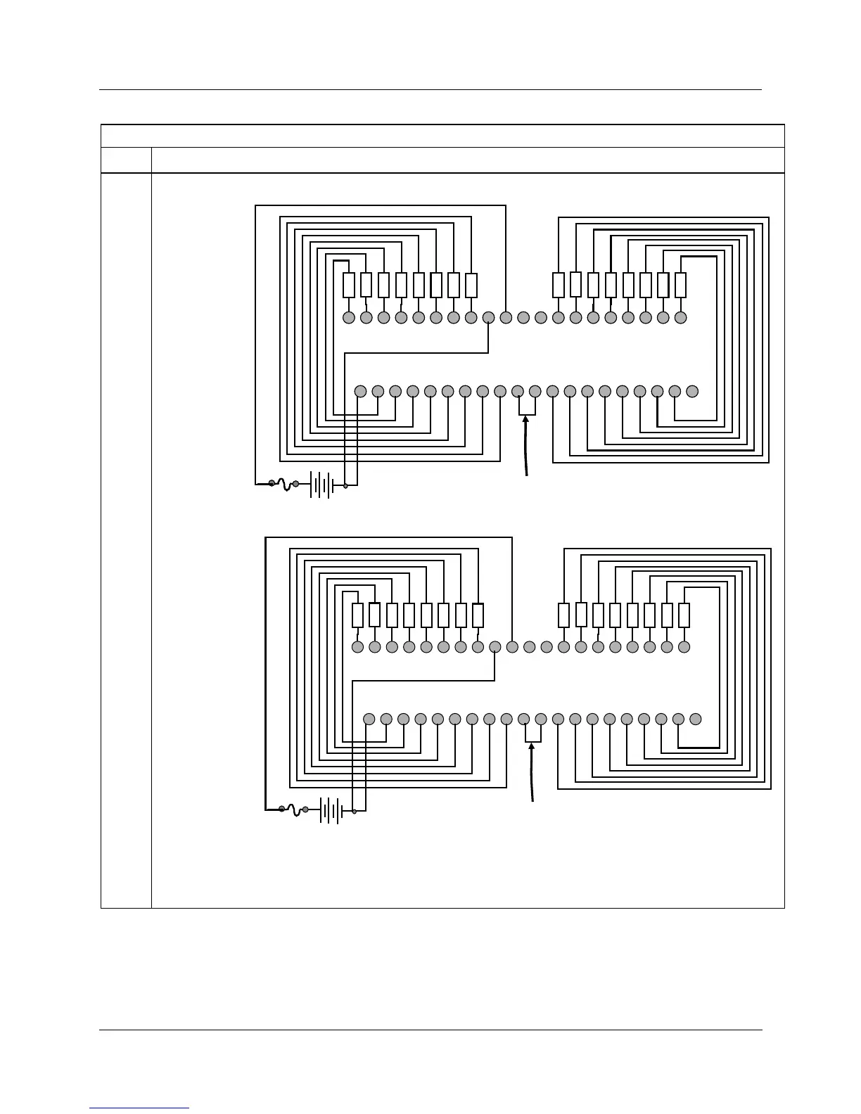
32 Point DC Digital Output
Step Action
4 Connect field wiring.
RTP A for
outputs 1 to 16
1 2 3 4 5 6 7 8 9 10 11 12 13 14 15 16 17 18 19 20
21 22 23 24 25 26 27 28 29 30 31 32 33 34 35 36 37 38 39 40
OUT1
OUT2
OUT3
OUT4
OUT5
OUT6
OUT7
OUT8
OUT9
OUT10
OUT11
OUT12
OUT13
OUT14
OUT15
OUT16
DC Supply
LOAD
LOAD
LOAD
LOAD
LOAD
LOAD
LOAD
LOAD
LOAD
LOAD
LOAD
LOAD
LOAD
LOAD
LOAD
LOAD
SDC
-
SDC
-
DC
-
SDC
-
SDC
-
SDC
-
SDC
-
SDC
-
SDC
-
SDC
-
SDC
-
SDC
-
SDC
-
SDC
-
SDC
-
SDC
-
SDC
-
SDC
-
SDC
-
SDC
-
DO1
DO2
DO9
DO10
DO5
DO6
DC+
DO3
DO4
DO7
DO8
DC
-
DC
-
DC+
DO11
DO12
DO13
DO14
DO15
DO16
Install jumper wire
RTP B for outputs
17 to 32
1 2 3 4 5 6 7 8 9 10 11 12 13 14 15 16 17 18 19 20
21 22 23 24 25 26 27 28 29 30 31 32 33 34 35 36 37 38 39 40
OUT17
OUT18
OUT19
OUT20
OUT21
OUT22
OUT23
OUT24
OUT25
OUT26
OUT27
OUT28
OUT29
OUT30
OUT31
OUT32
DC Supply
LOAD
LOAD
LOAD
LOAD
LOAD
LOAD
LOAD
LOAD
LOAD
LOAD
LOAD
LOAD
LOAD
LOAD
LOAD
LOAD
SDC
-
SDC
-
DC
-
SDC
-
SDC
-
SDC
-
SDC
-
SDC
-
SDC
-
SDC
-
SDC
-
SDC
-
SDC
-
SDC
-
SDC
-
SDC
-
SDC
-
SDC
-
SDC
-
SDC
-
DO17
DO18
DO25
DO26
DO21
DO22
DC+
DO19
DO20
DO23
DO24
DC
-
DC
-
DC+
DO27
DO28
DO29
DO30
DO31
DO32
Install jumper wire
Note: SDC- refers to the switched negative side of the DC supply.
Note: Terminals 9 and 11 (DC-) are connected through the RTP cable. Same for terminals 10 and 12 (DC+).

 Loading...


