Pre-Installation Planning - Cable/Wiring Distance Planning
46 HC900 Process Controller Installation and User Guide Revision 19
06/14
How to make Ethernet cables
Ethernet cable (shielded cable IO Cat 5) contains 4 twisted pairs of wires and a drain wire. Each pair
consists of a solid color wire and a color wire with a white stripe.
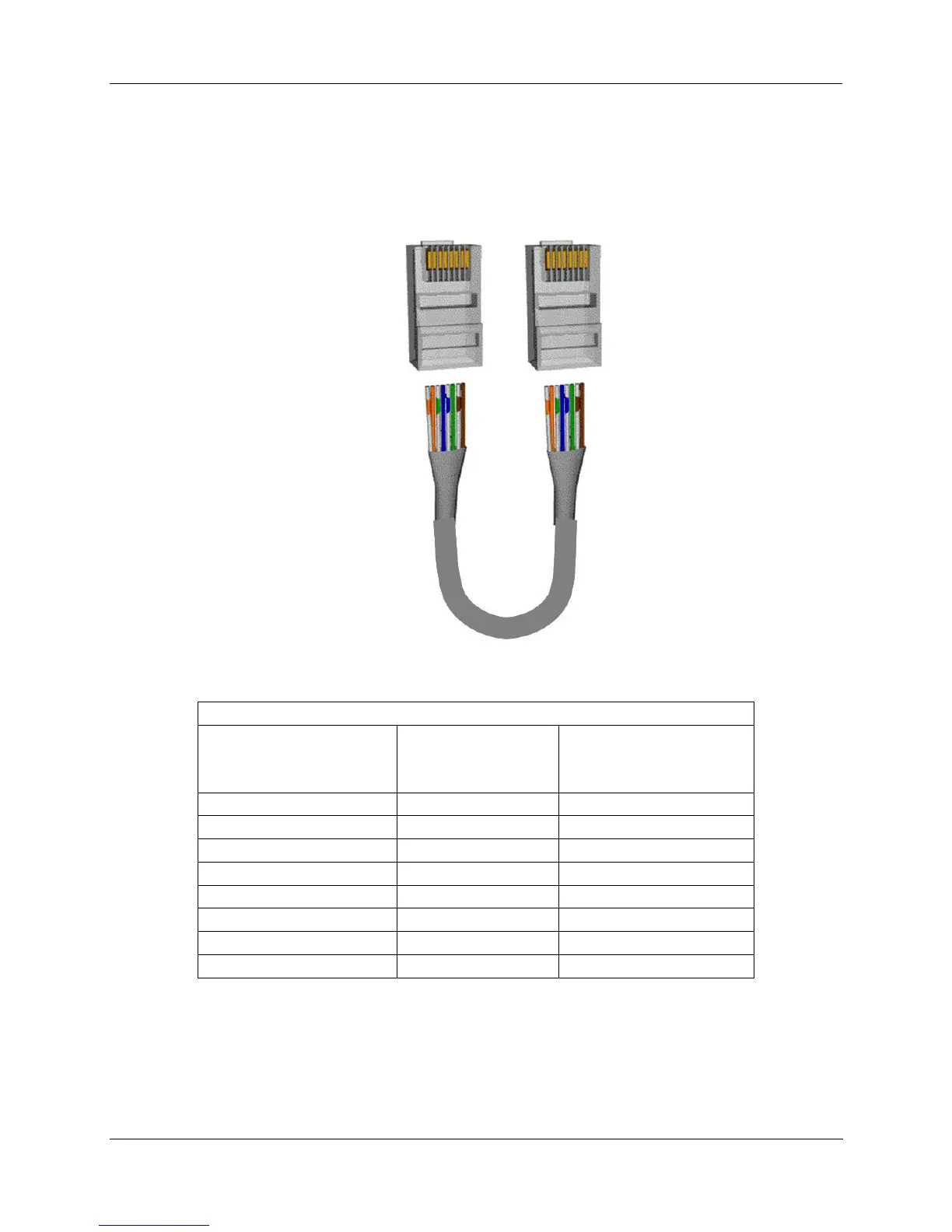
1. Hold the cable ends and RJ45 connectors side by side as shown:
2. For straight through cable, arrange wires as shown in the following table. Wires go “straight through”,
no crossovers.
Straight-through cable assembly
Cable left end
Left to right
Wire color/pin number
10Base-T / 100Base-T
Signal Description
Cable right end
Left to right
Wire color/pin number
white/orange/1 Tx + white/orange/1
Orange/2 Tx - Orange/2
white/green/3 Rx + white/green/3
Blue/4 Unused Blue/4
white/blue/5 Unused white/blue/5
Green/6 Rx - Green/6
white/brown/7 Unused white/brown/7
Brown/8 Unused Brown/8

 Loading...


