Rack Mounting Instructions
To rack mount the controller in the standard system cabinet (1600 mm height) of the HP
4062UX/F, the HP 4062UX/F must be equipped with option 701, 702, 703, 704, 705, or 706
(depending on the controller mo del and conguration) for rack mounting the controller. The
following paragraphs provide controller rack mounting information.
If the HP 4062UX/F is still in its shipping container, refer to chapter 4, \Receiving," in the
HP 4062UX/F
Pre-instal lation Manual
and unpack the cartons before continuing with this
chapter.
Note
You cannot mount the controller or mass storage unit in the small system
cabinet (1000 mm height) of the HP 4062UX. There is no space for mounting
any instruments other than system instruments.
Installing Controller and Backplane Expander (Option 701, 702, 703, or 704)
The rack mount kits are installed in the system cabinet at the factory. Before executing the
rack mounting, remove the rack mount kits from the system cabinet.
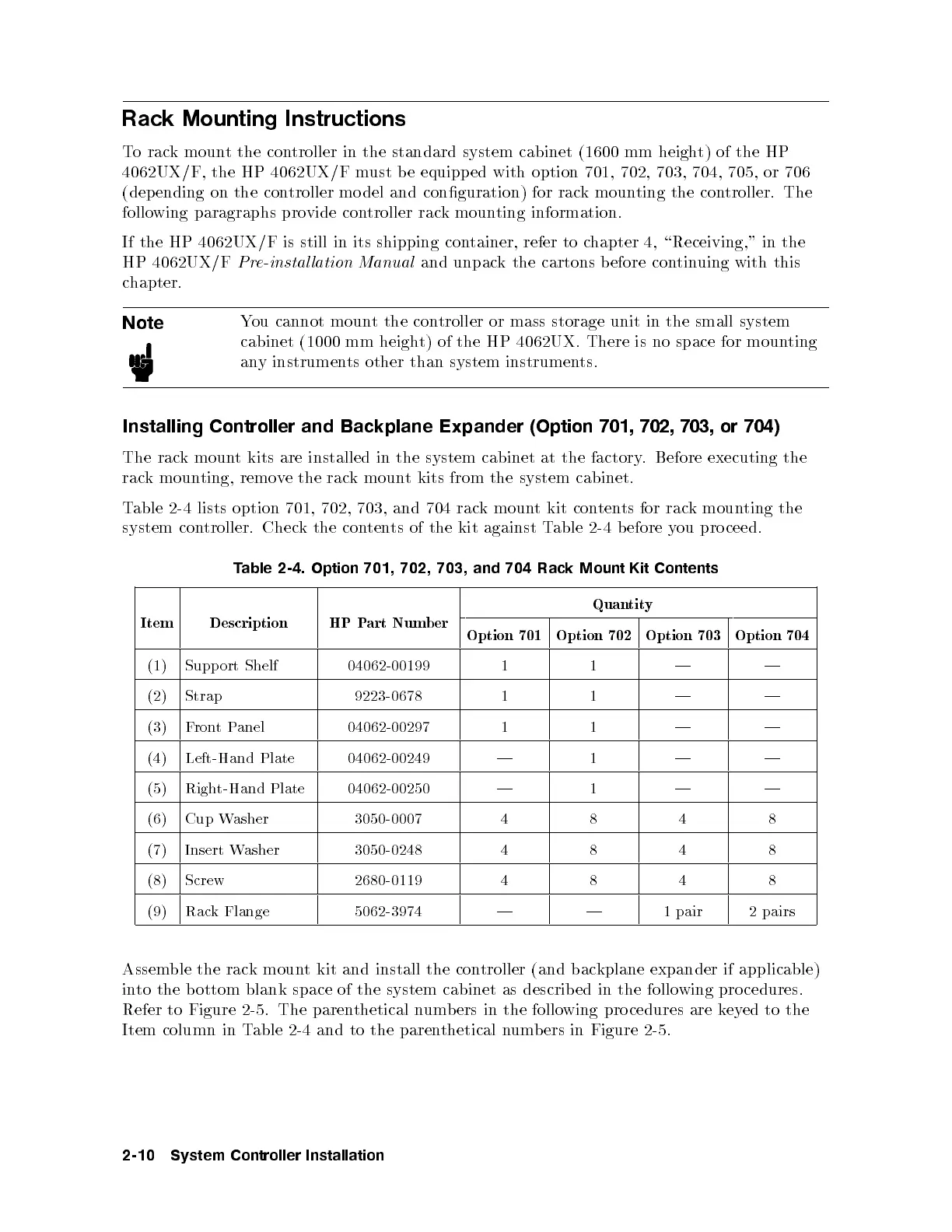
Table 2-4 lists option 701, 702, 703, and 704 rac
k mount kit contents for rack mounting the
system controller. Check the contents of the kit against Table 2-4 before you pro ceed.
Table 2-4. Option 701, 702, 703, and 704 Rack Mount Kit Contents
Item Description HP Part Number
Quantity
Option 701 Option 702 Option 703 Option 704
(1) Support Shelf 04062-00199 1 1 | |
(2) Strap 9223-0678 1 1 | |
(3) FrontPanel 04062-00297 1 1 | |
(4) Left-Hand Plate 04062-00249 | 1 | |
(5) Right-Hand Plate 04062-00250 | 1 | |
(6) Cup Washer 3050-0007 4 8 4 8
(7) Insert Washer 3050-0248 4 8 4 8
(8) Screw 2680-0119 4 8 4 8
(9) Rack Flange 5062-3974 | | 1 pair 2 pairs
Assemble the rack mount kit and install the controller (and backplane expander if applicable)
into the bottom blank space of the system cabinet as describ ed in the following procedures.
Refer to Figure 2-5. The parenthetical numbers in the following pro cedures are keyed to the
Item column in Table 2-4 and to the parenthetical numbers in Figure 2-5.
2-10 System Controller Installation