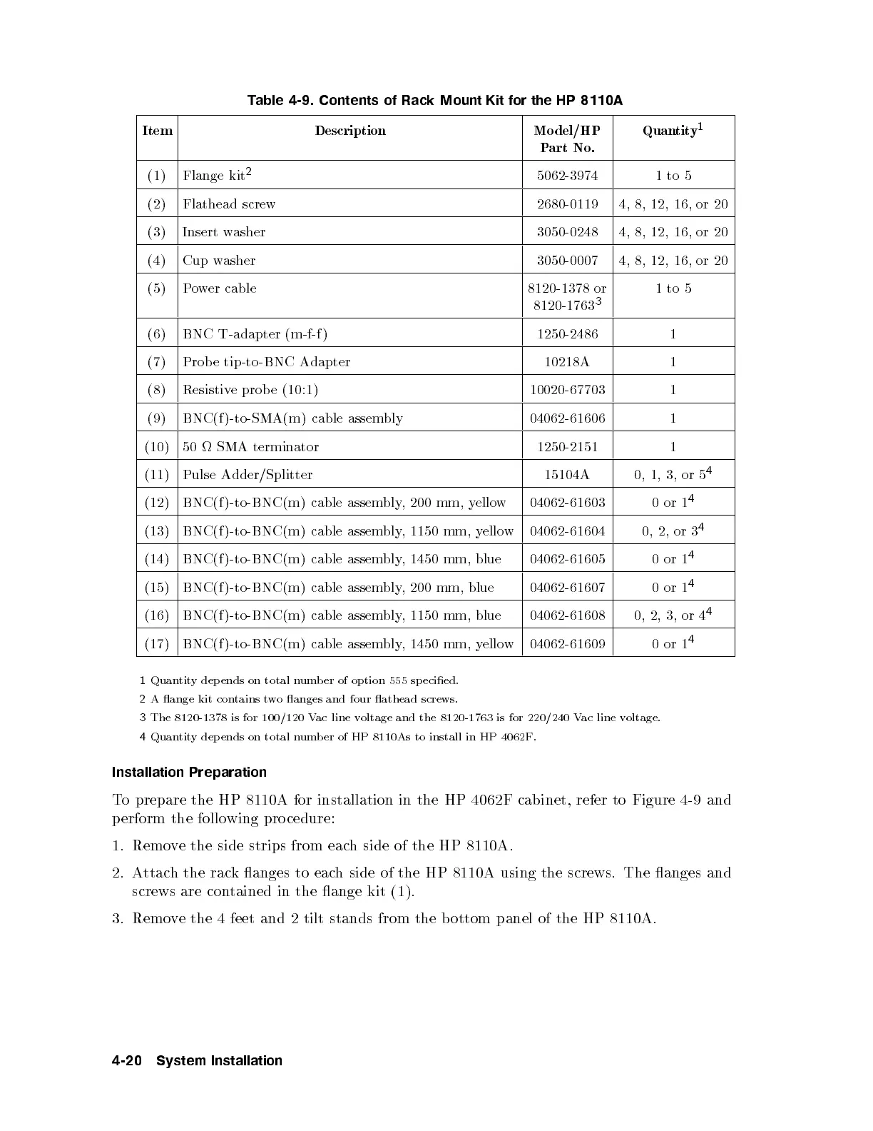
Table 4-9. Contents of Rack Mount Kit for the HP 8110A
Item Description Model/HP
Part No.
Quantity
1
(1) Flange kit
2
5062-3974 1to 5
(2) Flathead screw 2680-0119 4, 8, 12, 16, or 20
(3) Insert washer 3050-0248 4, 8, 12, 16, or 20
(4) Cup washer 3050-0007 4, 8, 12, 16, or 20
(5) Power cable 8120-1378 or
8120-1763
3
1to 5
(6) BNC T-adapter (m-f-f ) 1250-2486 1
(7) Probe tip-to-BNC Adapter 10218A 1
(8) Resistive prob e (10:1) 10020-67703 1
(9) BNC(f )-to-SMA(m) cable assembly 04062-61606 1
(10) 50 SMA terminator 1250-2151 1
(11) Pulse Adder/Splitter 15104A 0, 1, 3, or 5
4
(12) BNC(f )-to-BNC(m) cable assembly, 200 mm, yellow
04062-61603 0or 1
4
(13) BNC(f )-to-BNC(m) cable assembly, 1150 mm, yellow
04062-61604 0, 2, or 3
4
(14) BNC(f )-to-BNC(m) cable assembly, 1450 mm, blue 04062-61605 0or1
4
(15) BNC(f )-to-BNC(m) cable assembly, 200 mm, blue 04062-61607 0or 1
4
(16) BNC(f )-to-BNC(m) cable assembly, 1150 mm, blue 04062-61608 0, 2, 3, or 4
4
(17) BNC(f )-to-BNC(m) cable assembly, 1450 mm, yellow
04062-61609 0or 1
4
1
Quantity dep ends on total numb er of option 555 sp ecied.
2
A ange kit contains two anges and four athead screws.
3
The 8120-1378 is for 100/120 Vac line voltage and the 8120-1763 is for 220/240 Vac line voltage.
4
Quantity dep ends on total numb er of HP 8110As to install in HP 4062F.
Installation Preparation
To prepare the HP 8110A for installation in the HP 4062F cabinet, refer to Figure 4-9 and
perform the follo wing procedure:
1. Remove the side strips from each side of the HP 8110A.
2. Attach the rack anges to each side of the HP 8110A using the screws. The anges and
screws are contained in the ange kit (1).
3. Remove the 4 feet and 2 tilt stands from the b ottom panel of the HP 8110A.
4-20 System Installation