HP 4142B DCS Settings
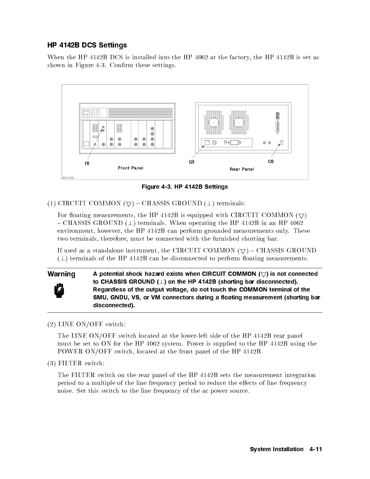
When the HP 4142B DCS is installed into the HP 4062 at the factory, the HP 4142B is set as
shown in Figure 4-3. Conrm these settings.
Figure 4-3. HP 4142B Settings
(1) CIRCUIT COMMON (
5
) { CHASSIS GROUND (
?
) terminals:
For oating measurements, the HP 4142B is equipped with CIR
CUIT COMMON (
5
)
{ CHASSIS GROUND (
?
) terminals. When op erating the HP 4142B in an HP 4062
environment, however, the HP 4142B can perform grounded measuremen
ts only. These
two terminals, therefore, must be connected with the furnished shorting bar.
If used as a standalone instrument, the CIRCUIT COMMON (
5
) { CHASSIS GROUND
(
?
) terminals of the HP 4142B can b e disconnected to p erform oating measuremen
ts.
Warning
A potential shock hazard exists when CIRCUIT COMMON (
5
) is not connected
to CHASSIS GROUND (
?
) on the HP 4142B (shorting bar disconnected).
Regardless of the output voltage, do not touch the COMMON terminal of the
SMU, GNDU, VS, or VM connectors during a floating measurement (shorting bar
disconnected).
(2) LINE ON/OFF switch:
The LINE ON/OFF switch lo cated at the lower-left side of the HP 4142B rear panel
must be set to ON for the HP 4062 system. P
ower is supplied to the HP 4142B using the
POWER ON/OFF switch, lo cated at the front panel of the HP 4142B.
(3) FILTER switch:
The FILTER switch on the rear panel of the HP 4142B sets the measurementintegration
perio d to a multiple of the line frequency perio d to reduce the eects of line frequency
noise. Set this switch to the line frequency of the ac p ower source.
System Installation 4-11