Although the cables from the system cabinet are ab out 4 m long, p osition the SWM less than
2 m from the system cabinet. Also, if the SWM is installed on a wafer prob er, make sure
there is enough slack in the cables so that the SWM can b e easily raised and lowered.
Caution
Do not use cables or cable assemblies other than those supplied with the
system. Use of other cables may damage the instruments or may makeit
imp ossible to obtain sp ecied measurement accuracy.
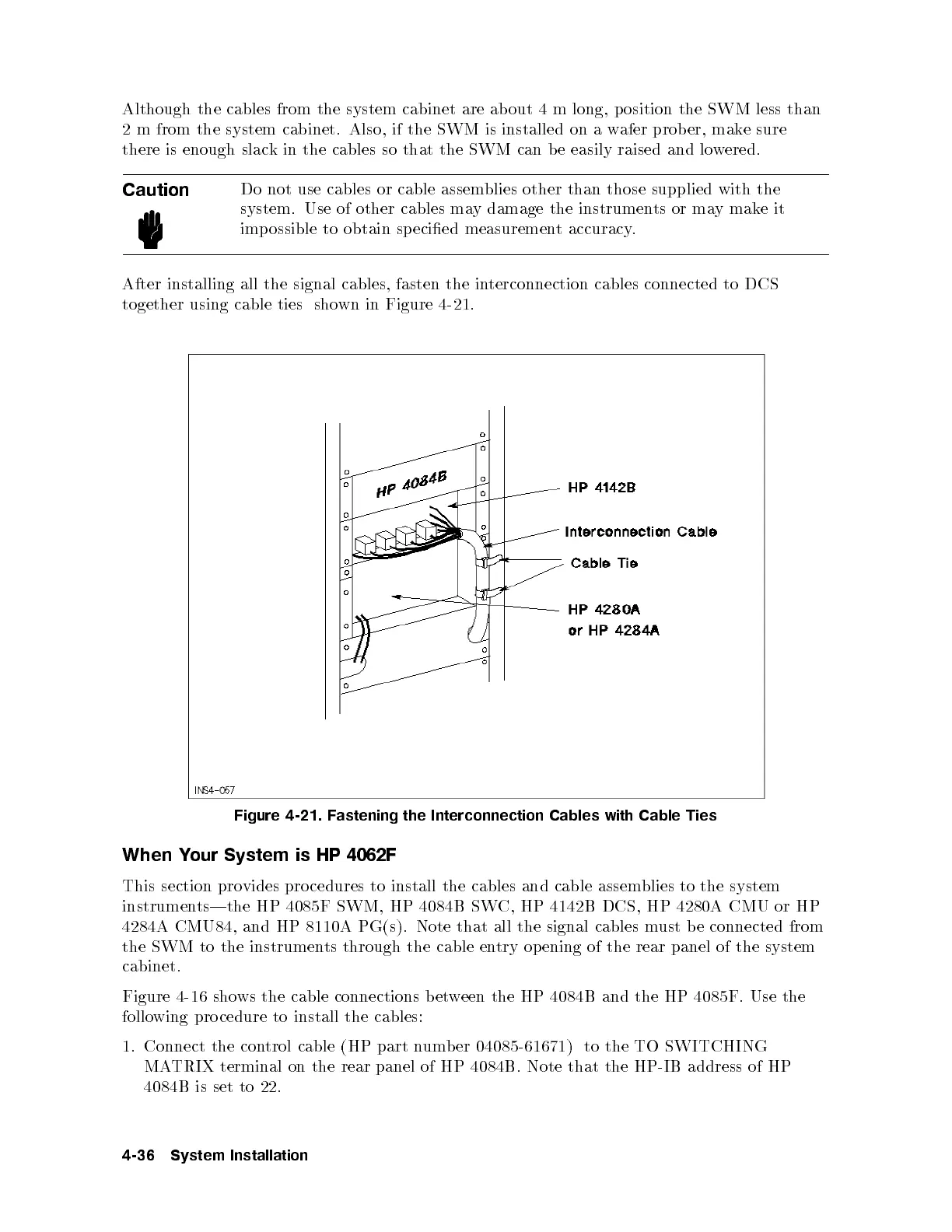
After installing all the signal cables, fasten the interconnection cables connected to DCS
together using cable ties shown in Figure 4-21.
Figure 4-21. Fastening the Interconnection Cables with Cable Ties
When Your System is HP 4062F
This section provides procedures to install the cables and cable assem
blies to the system
instruments|the HP 4085F SWM, HP 4084B SWC, HP 4142B DCS, HP 4280A CMU or HP
4284A CMU84, and HP 8110A PG(s). Note that all the signal cables must b e connected from
the SWM to the instruments through the cable entry op ening of the rear panel of the system
cabinet.
Figure 4-16 shows the cable connections between the HP 4084B and the HP 4085F. Use the
following pro cedure to install the cables:
1. Connect the control cable (HP part number 04085-61671) to the TO SWITCHING
MATRIX terminal on the rear panel of HP 4084B. Note that the HP-IB address of HP
4084B is set to 22.
4-36 System Installation