Mass Storage Unit
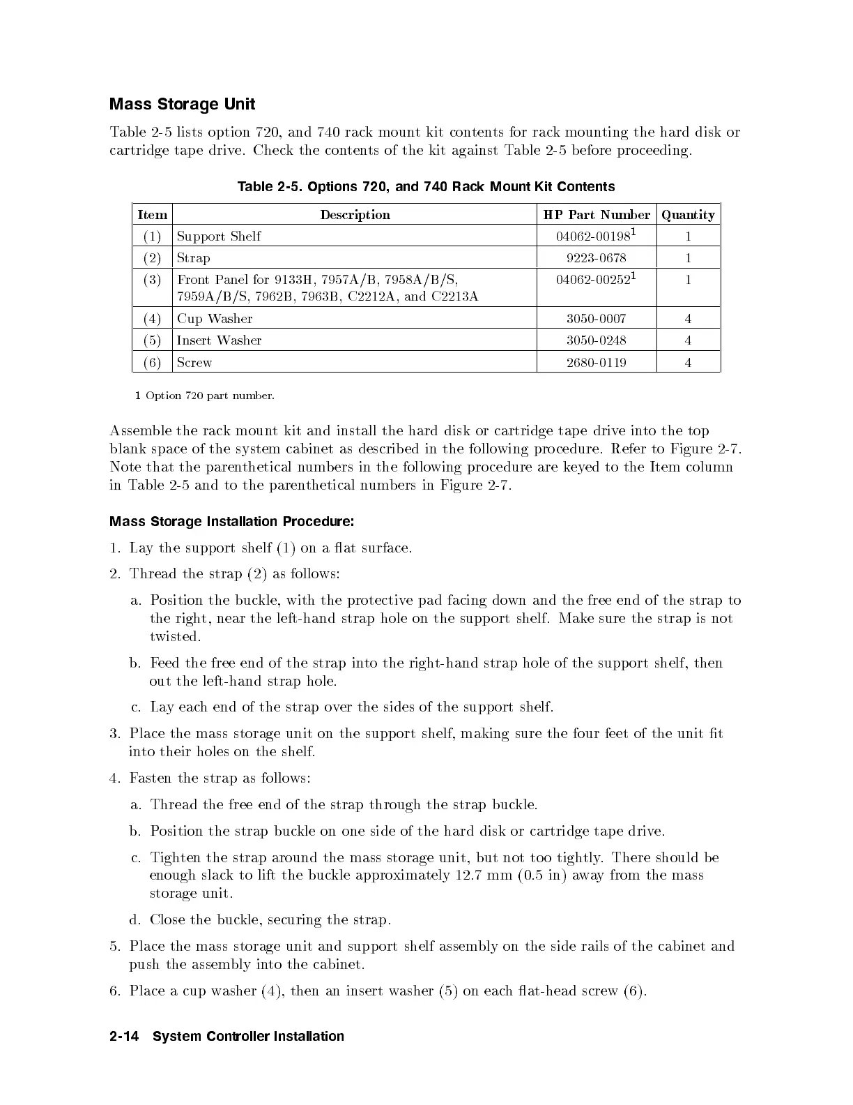
Table 2-5 lists option 720, and 740 rack mount kit contents for rack mounting the hard disk or
cartridge tap e drive. Check the contents of the kit against Table 2-5 b efore proceeding.
Table 2-5. Options 720, and 740 Rack Mount Kit Contents
Item Description HP Part Number Quantity
(1) Support Shelf 04062-00198
1
1
(2) Strap 9223-0678 1
(3) FrontPanel for 9133H, 7957A/B, 7958A/B/S,
7959A/B/S, 7962B, 7963B, C2212A, and C2213A
04062-00252
1
1
(4) Cup Washer 3050-0007 4
(5) Insert Washer 3050-0248 4
(6) Screw 2680-0119 4
1
Option 720 part number.
Assemble the rack mount kit and install the hard disk or cartridge tap e driv
einto the top
blank space of the system cabinet as described in the follo
wing pro cedure. Refer to Figure 2-7.
Note that the parenthetical numb ers in the following pro cedure are keyed to the Item column
in Table 2-5 and to the parenthetical numb ers in Figure 2-7.
Mass Storage Installation Procedure:
1. Lay the support shelf (1) on a at surface.
2. Thread the strap (2) as follows:
a. Position the buckle, with the protective pad facing down and the free end of the strap to
the right, near the left-hand strap hole on the support shelf. Mak
e sure the strap is not
twisted.
b. Feed the free end of the strap into the right-hand strap hole of the support shelf, then
out the left-hand strap hole.
c. Lay each end of the strap over the sides of the support shelf.
3. Place the mass storage unit on the support shelf, making sure the four feet of the unit t
into their holes on the shelf.
4. Fasten the strap as follows:
a. Thread the free end of the strap through the strap buckle.
b. Position the strap buckle on one side of the hard disk or cartridge tap e drive.
c. Tighten the strap around the mass storage unit, but not to o tightly. There should be
enough slack to lift the buckle approximately 12.7 mm (0.5 in) away from the mass
storage unit.
d. Close the buckle, securing the strap.
5. Place the mass storage unit and support shelf assem
bly on the side rails of the cabinet and
push the assembly into the cabinet.
6. Place a cup washer (4), then an insert washer (5) on each at-head screw (6).
2-14 System Controller Installation