Installing Additional Pin Boards
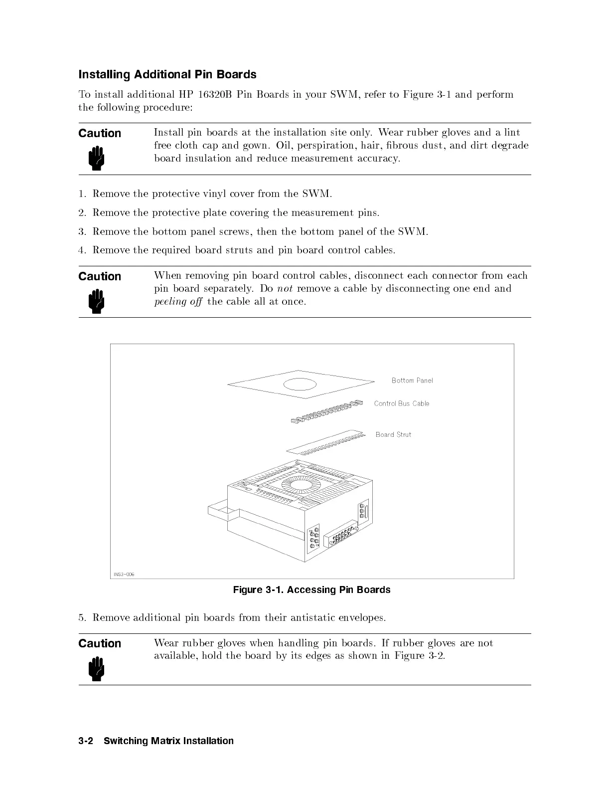
To install additional HP 16320B Pin Boards in your SWM, refer to Figure 3-1 and perform
the follo wing procedure:
Caution
Install pin boards at the installation site only.Wear rubber gloves and a lint
free cloth cap and gown. Oil, perspiration, hair, brous dust, and dirt degrade
board insulation and reduce measurement accuracy.
1. Remove the protective vinyl cover from the SWM.
2. Remove the protective plate covering the measurement pins.
3. Remove the bottom panel screws, then the b ottom panel of the SWM.
4. Remove the required board struts and pin board control cables.
Caution
When removing pin b oard control cables, disconnect each connector from each
pin b oard separately.Do
not
remove a cable by disconnecting one end and
peeling o
the cable all at once.
Figure 3-1. Accessing Pin Boards
5. Remove additional pin b oards from their antistatic envelop es.
Caution
Wear rubber gloves when handling pin b oards. If rubber gloves are not
available, hold the b oard by its edges as shown in Figure 3-2.
3-2 Switching Matrix Installation