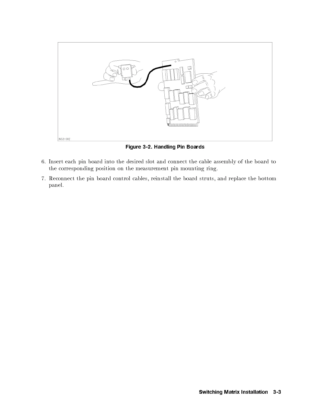
Figure 3-2. Handling Pin Boards
6. Insert each pin b oard into the desired slot and connect the cable assem
bly of the b oard to
the corresp onding p osition on the measurement pin mounting ring.
7. Reconnect the pin b oard control cables, reinstall the board struts, and replace the b ottom
panel.
Switching Matrix Installation 3-3