If the BNC-to-SMA cable assembly (9) is not installed in the system cabinet, use the
following pro cedure to install:
a. Attach a BNC T-adapter (6) to the TRIGGER OUT terminal on the rear panel of the
top HP 8110A (PG1).
b. Attach a prob e tip-to-BNC adapter (7) to the BNC T-adapter (6).
c. Connect a resistive probe (8) to the prob e tip-to-BNC adapter.
d. Connect a BNC-to-SMA cable assembly (9) to the resistive prob e.
e. Connect a 50 SMA terminator (10) to the BNC-to-SMA cable assembly.
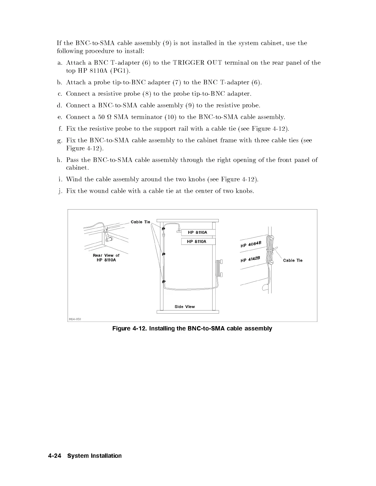
f. Fix the resistive probe to the support rail with a cable tie (see Figure 4-12).
g. Fix the BNC-to-SMA cable assembly to the cabinet frame with three cable ties (see
Figure 4-12 ).
h. Pass the BNC-to-SMA cable assembly through the right opening of the front panel of
cabinet.
i. Wind the cable assembly around the two knobs (see Figure 4-12).
j. Fix the wound cable with a cable tie at the cen
ter of two knobs.
Figure 4-12. Installing the BNC-to-SMA cable assembly
4-24 System Installation