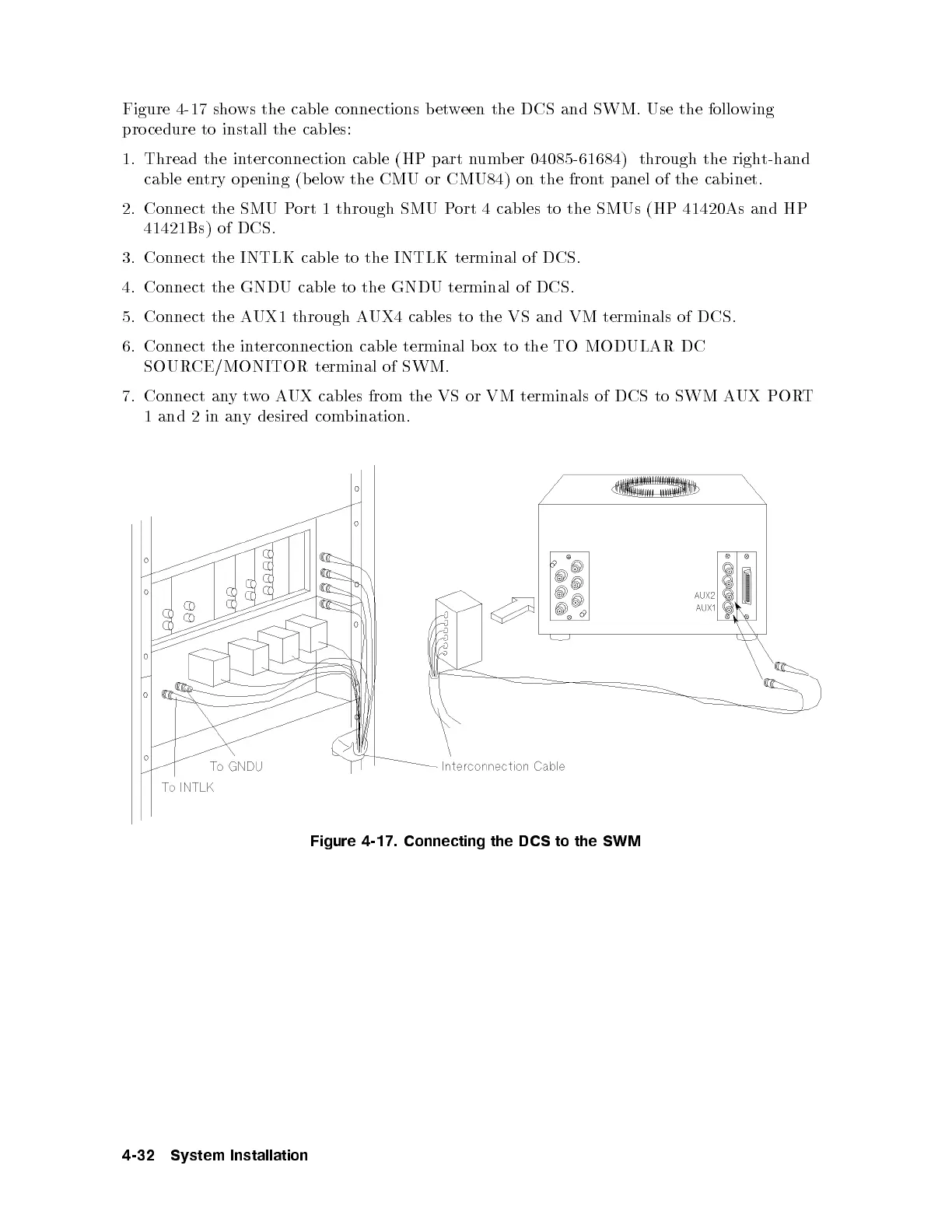
Figure 4-17 shows the cable connections between the DCS and SWM. Use the following
pro cedure to install the cables:
1. Thread the interconnection cable (HP part numb er 04085-61684) through the right-hand
cable entry opening (b elow the CMU or CMU84) on the front panel of the cabinet.
2. Connect the SMU Port 1 through SMU Port 4 cables to the SMUs (HP 41420As and HP
41421Bs) of DCS.
3. Connect the INTLK cable to the INTLK terminal of DCS.
4. Connect the GNDU cable to the GNDU terminal of DCS.
5. Connect the AUX1 through AUX4 cables to the VS and VM terminals of DCS.
6. Connect the interconnection cable terminal box to the TO MODULAR DC
SOURCE/MONITOR terminal of SWM.
7. Connect anytwoAUX cables from the VS or VM terminals of DCS to SWM AUX PORT
1 and 2 in any desired combination.
Figure 4-17. Connecting the DCS to the SWM
4-32 System Installation