How the Instrument Works
System Architecture
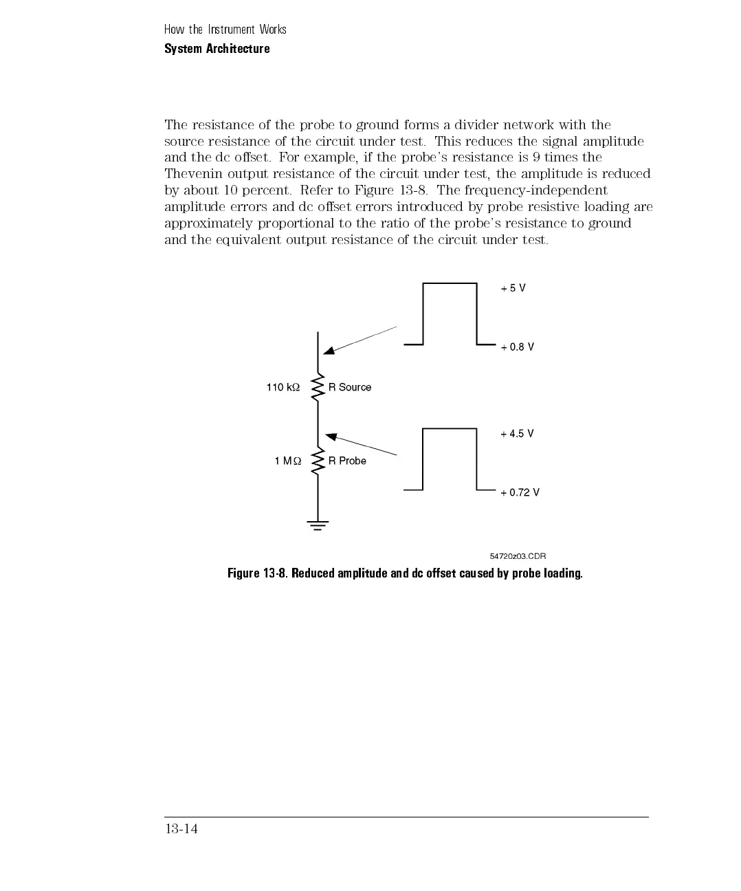
The resistance of the probe to ground forms a divider network with the
source resistance of the circuit under test. This reduces the signal amplitude
and the dc oset. For example, if the probe's resistance is 9 times the
Thevenin output resistance of the circuit under test, the amplitude is reduced
by about 10 percent. Refer to Figure 13-8. The frequency-independent
amplitude errors and dc oset errors introduced by probe resistive loading are
approximately proportional to the ratio of the probe's resistance to ground
and the equivalent output resistance of the circuit under test.
Figure 13-8. Reduced amplitude and dc oset caused by probe loading.
13-14