How the Instrument Works
Standard and Enhanced Trigger Modes
Figure 13-17 shows the eect of the modulus 16 trigger, where the carrier
within the envelope is \smeared" because the trigger may occur on any of the
rst sixteen carrier cycles. However, the envelope information is still visible.
For some signals, such as eye diagrams, this eect is not important. In other
cases, it may be possible to adjust the signal to be of modulus 16 so that the
trigger is stationary.
Gate Enable False
Triggers
In this gating architecture, if the trigger input is high when the gate enable is
asserted, there is a nite chance that a false analyzer trigger will result.
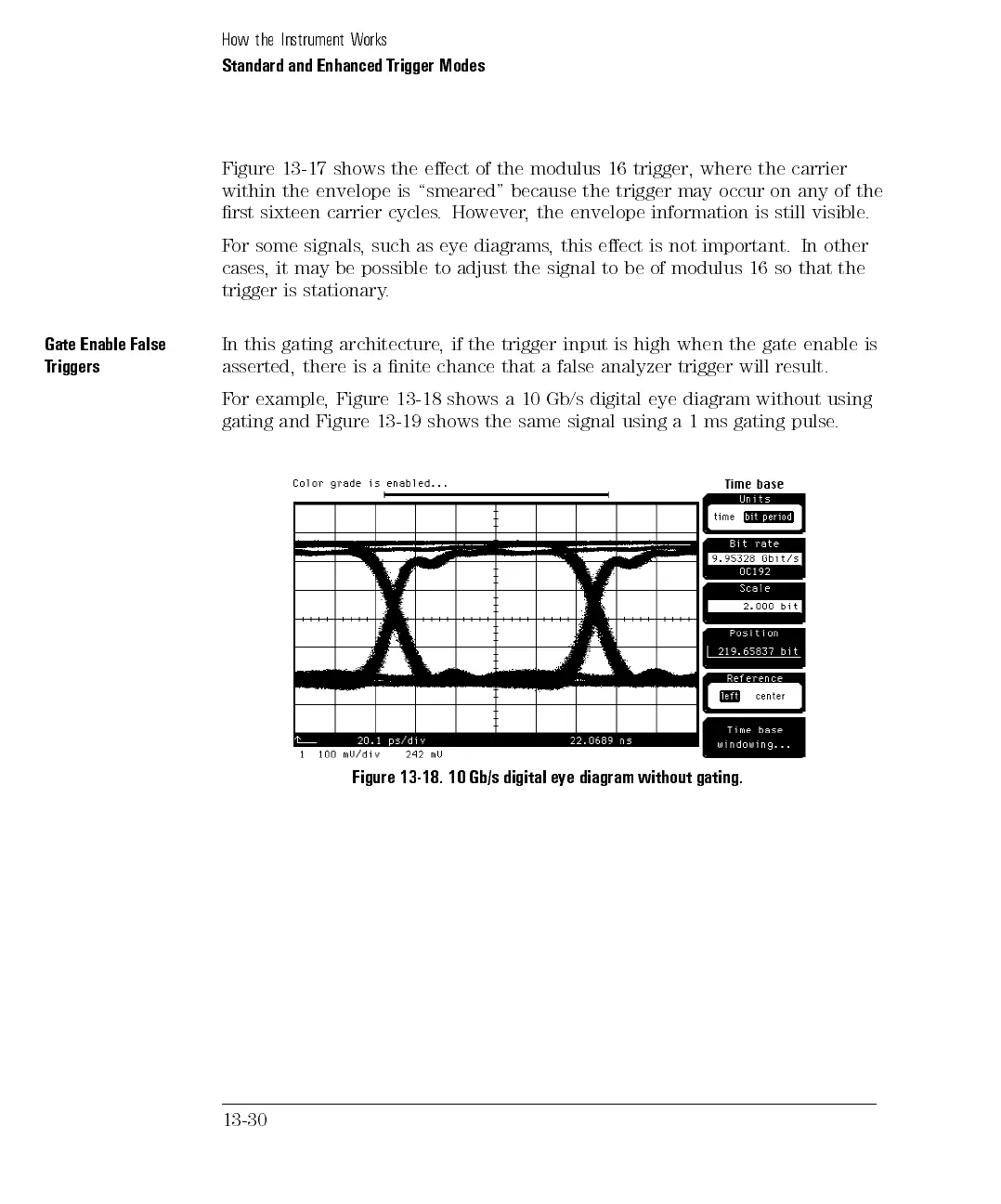
For example, Figure 13-18 shows a 10 Gb/s digital eye diagram without using
gating
and
Figure
13-19
shows
the
same
signal
using
a
1
ms
gating
pulse
.
Figure 13-18. 10 Gb/s digital eye diagram without gating.
13-30