How the Instrument Works
System Architecture
Perhaps you have connected an analyzer to a circuit for troubleshooting
only to have the circuit operate correctly after connecting the probes. The
capacitive loading of the probes can attenuate a glitch, remove ringing or
overshoot, or slow an edge just enough that a setup or hold time violation no
longer occurs.
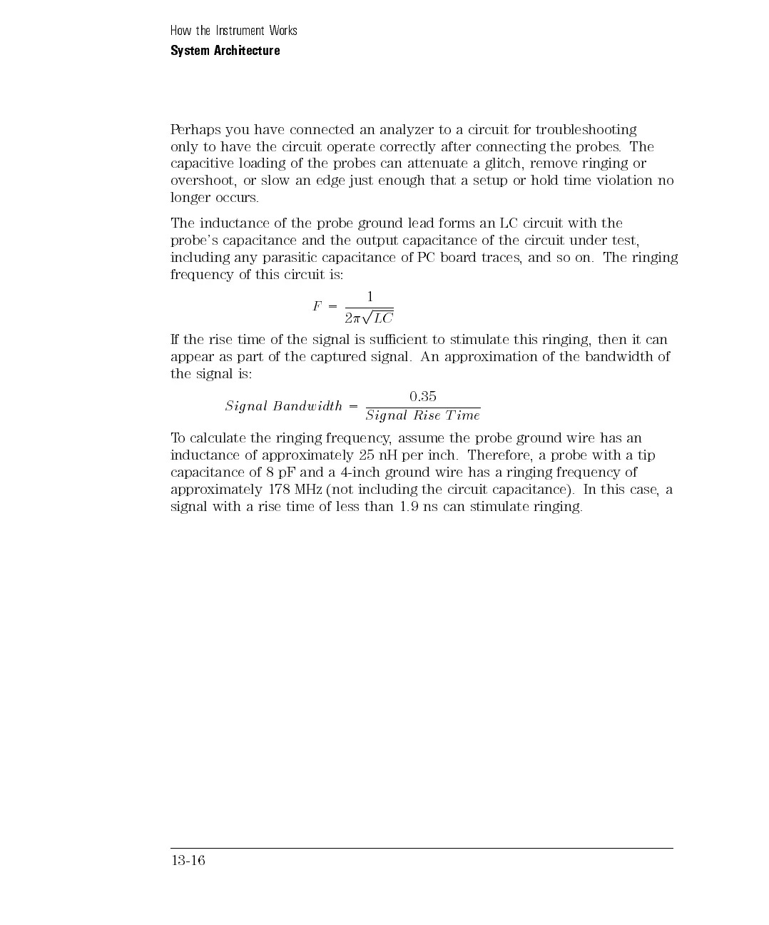
The inductance of the probe ground lead forms an LC circuit with the
probe's capacitance and the output capacitance of the circuit under test,
including any parasitic capacitance of PC board traces, and so on. The ringing
frequency of this circuit is:
F
=
1
2
p
LC
If
the
rise
time
of
the
signal
is
sucient
to
stimulate
this
ringing,
then
it
can
appear
as
part
of
the
captured
signal.
An
approximation
of
the
bandwidth
of
the
signal
is:
S
ig
nal
B
andw
idth
=
0
:
35
S
ig
nal
R
ise
T
ime
T
o
calculate
the
ringing
frequency
,
assume
the
probe
ground
wire
has
an
inductance
of
approximately
25
nH
per
inch.
Therefore
,
a
probe
with
a
tip
capacitance
of
8
pF
and
a
4-inch
ground
wire
has
a
ringing
frequency
of
approximately 178
MHz
(not
including
the
circuit
capacitance).
In
this
case
,
a
signal with
arise
time
of
less
than
1.9
ns
can
stimulate
ringing.
13-16
 Loading...