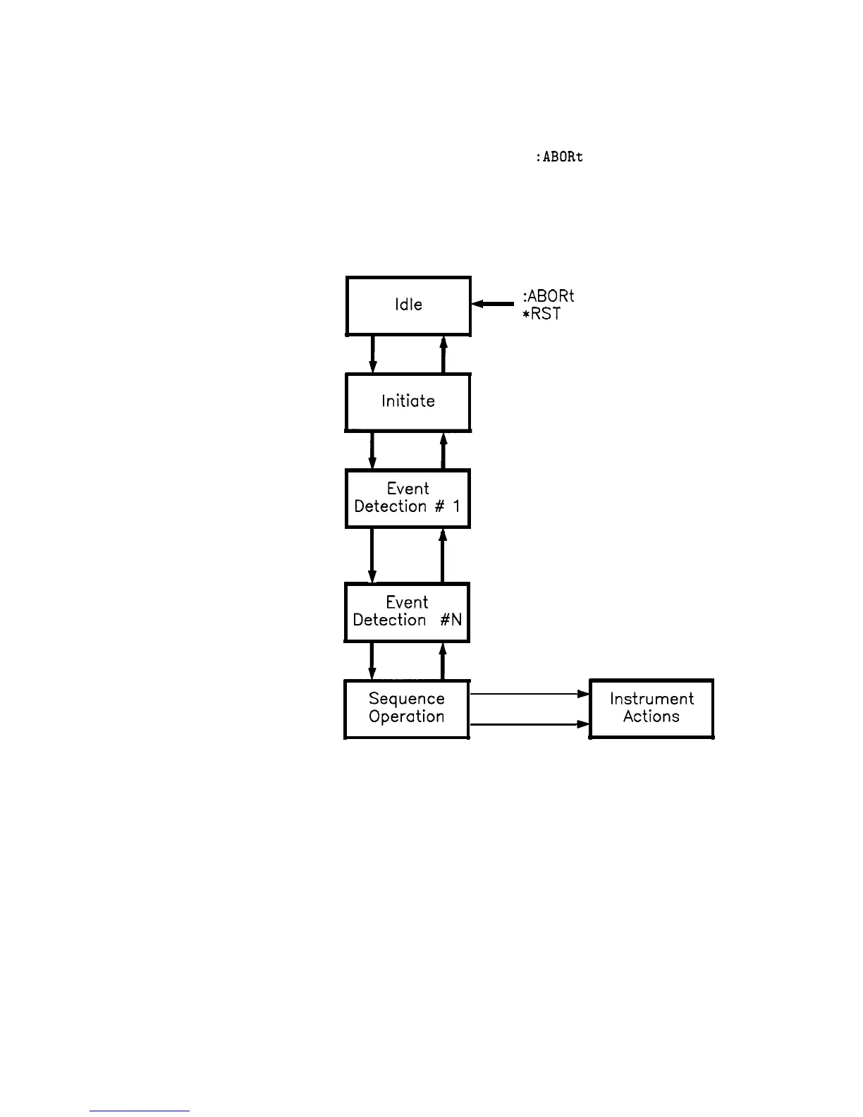
An instrument moves between adjacent states, depending on its
internal conditions and the commands that you send. When you first
turn on power to an instrument, it is in the idle state. You can force
the instrument to the idle state using
:ABORt
or *RST.
The initiate
and event detection trigger states are essentially a list of conditions
that must be satisfied to reach the adjacent states. The sequence
operation state signals the instrument hardware to take some action,
and listens for a signal that the action has been taken.
Idle
_
:ABORt
*RST
Initiate
Event
Detection #
1
A
v
Event
Detection #N
Sequence
*
Instrument
Operation
*
Actions
Figure 1-35. Generalized Trigger Model
Details of Trigger States
These paragraphs use flow charts to explain the decision making rules
inside each trigger state. These rules govern how the instrument
moves between adjacent states. Some of the flow charts reference
commands that have not been discussed yet. These commands
are explained later in this subsection. Keep in mind that this
explanation covers the most general case. Your particular instrument
may not implement all of the commands discussed here.
l-1 10
Getting Started Programming

 Loading...


