Creating a User Flatness Array Automatically, Example 1
In this example, a flatness array containing correction frequencies
from 4 to 10 GHz at 1 GHz intervals is created. An HP 438B power
meter controlled by the swept signal generator through the interface
bus is used to enter the correction data into the flatness array.
For this example, refer to menu map 5, POWER.
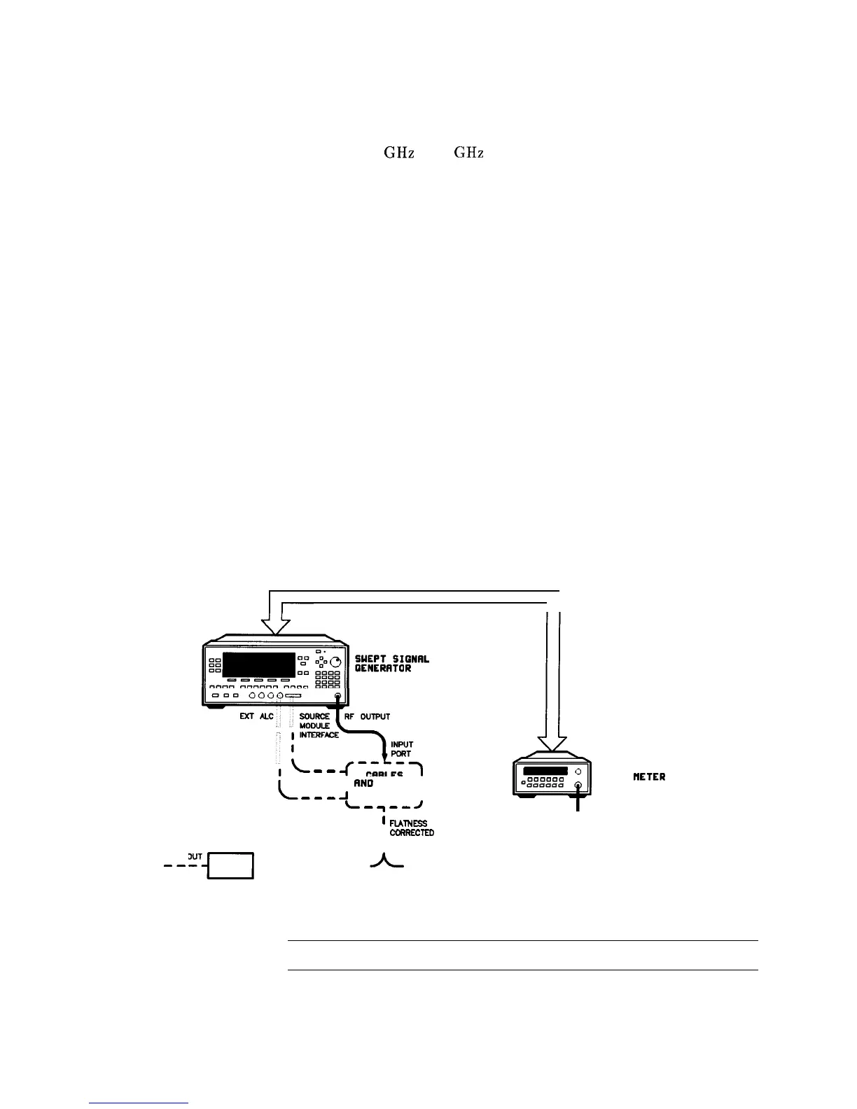
1. The equipment setup shown in Figure 1-18 assumes that if the
setup has an external leveling configuration, the steps necessary
to correctly level have been followed. If you have questions about
external leveling, refer to “Externally Leveling the Swept Signal
Generator”.
--
Setup Power Meter
2. Zero and calibrate the power meter/sensor.
3. Enter the appropriate power sensor calibration factors into the
power meter.
4. Enable the power meter/sensor cal factor array. For operating
information on the HP 437B power, refer to its operating and
service manual.
5. Connect the power sensor to the point where corrected power is
desired.
HP-IB
I
kTii&TFG
--
CABLES
I
RN0
OTHER I
B-B
J
DEVICES ,
L
-I”
I
b
-0
ooo~o~a
q DDDaa
HP 4378
POUER
HETER
1
FUINBS
I
coRREcTEo
, OUTPUT PORT
POUER SENSOR
OUT
-u
IN
---------
--B-m-
ud
DEVICE
UNDER
TEST
Figure 1-16. Creating a User Flatness Array Automatically
Note
No other devices can be connected to the HP-IB cable.
1-34 Getting Started Advanced

 Loading...


