Modulation
Modulation
General Circuit Theory
The swept signal generator’s amplitude and pulse modulation
performance is directly tied to the ALC (Automatic Level Control)
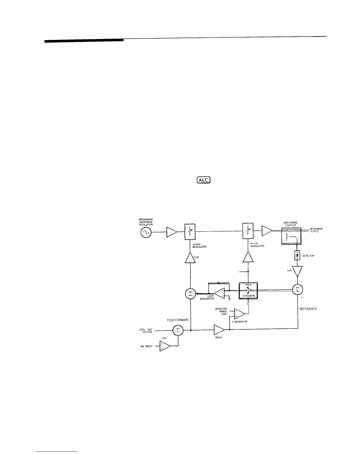
system. Refer to the ALC block diagram in Figure M-l. The ALC
system controls the amplitude or power level of the RF output.
A portion of the output signal is detected, summed with the
reference level signal, and the difference (error) signal drives an
integrate-and-hold circuit.
The integrator output drives the RF
output power level via the linear modulator. When the sum of the
detected and reference signals is 0 volts, the output of the integrator
is held at a constant level and the RF output is leveled. This loop
is bandwidth-limited by the integrator and the integrate-and-hold
circuit. Notice, however, that there is a feedforward path that allows
changes in power level that are bandwidth-independent from the
rest of the ALC loop. Power level information supplied by the
level DAC and AM input travels the feedforward path to drive a
linear modulator. (See
IALC)
for additional information on the ALC
system.)
PULSE INPUT
-I
Figure M-l. ALC Block Diagram
Operating and Programming Reference M-13

 Loading...


