EasyManuals Logo

HP HPE Synergy 12000 Frame User Manual

HP HPE Synergy 12000 Frame
183 pages
To Next Page IconTo Next Page
To Previous Page IconTo Previous Page
Page #41 background imageLoading...
Page #41 background image
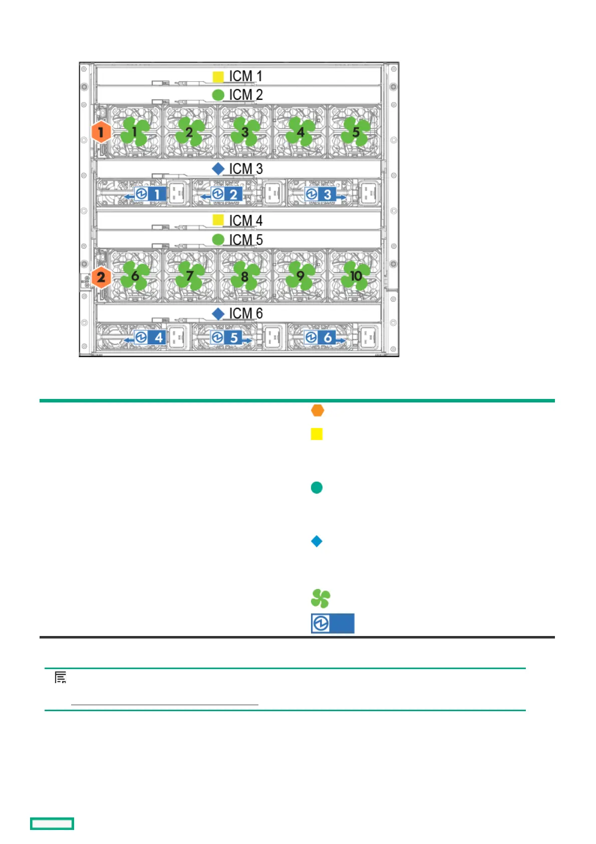
Rear component bay numberingRear component bay numbering
ComponentsComponents BaysBays LabelsLabels
Frame link modules 1 and 2
Interconnect modules
These interconnect modules are redundant pairs
on fabric 1.
1 and 4
Interconnect modules
These interconnect modules are redundant pairs
on fabric 2.
2 and 5
Interconnect modules
These interconnect modules are redundant pairs
on fabric 3.
3 and 6
Fans 1 through 10
Power supplies 1 through 6
NOTE: NOTE: The arrow direction on each of the power supply icons indicates the recommended power routing to either A-side
or B-side. For more information about A-side and B-side power distribution, see the HPE Synergy Cabling Guide (
https://www.hpe.com/info/synergy-cabling-guidehttps://www.hpe.com/info/synergy-cabling-guide).
Rear component bay numbering 41

Table of Contents

Other manuals for HP HPE Synergy 12000 Frame

Questions and Answers:

Question and Answer IconNeed help?

Do you have a question about the HP HPE Synergy 12000 Frame and is the answer not in the manual?

HP HPE Synergy 12000 Frame Specifications

General IconGeneral
Form FactorRack-mountable
Maximum Compute Modules12
Management ModuleHPE Synergy Composer
CoolingRedundant fan modules
Power SupplyRedundant power supplies
NetworkingHPE Synergy 12000 Frame Interconnect
Product TypeBlade Enclosure
Width44.5 cm
ComplianceFCC, VCCI, BSMI, CCC, KCC, RoHS
Depth36.25 in (92.08 cm)

Related product manuals