112
IP Address Type State Cost Pri DR BDR
192.168.1.2 Broadcast DROther 1 0 192.168.1.1 192.168.1.3
The interface state DROther means the interface is not the DR or BDR.
OSPF virtual link configuration example
Network requirements
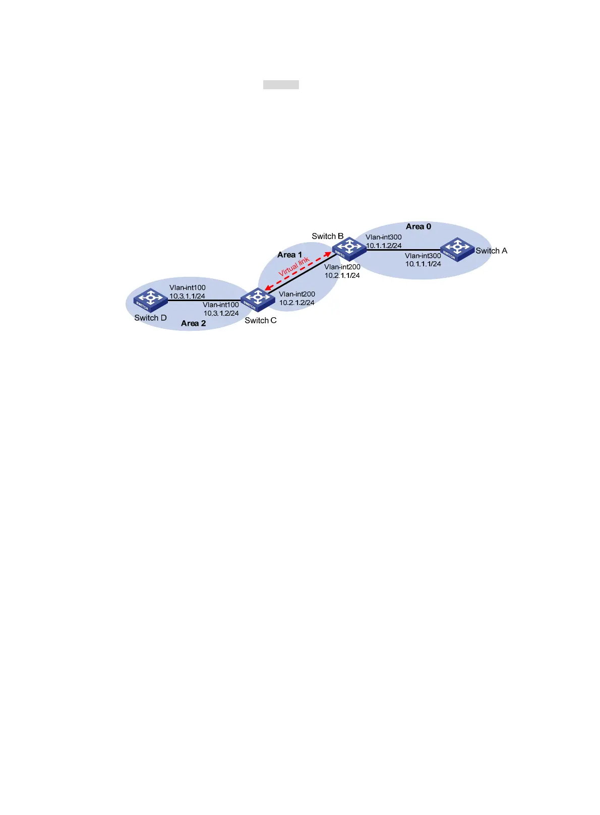
As shown in Figure 28, configure a virtual link between Switch B and Switch C to connect Area 2 to
the backbone area. After configuration, Switch B can learn routes to Area 2.
Figure 28 Network diagram
Configuration procedure
1. Configure IP addresses for interfaces. (Details not shown.)
2. Enable OSPF:
# Configure Switch A.
<SwitchA> system-view
[SwitchA] ospf 1 router-id 1.1.1.1
[SwitchA-ospf-1] area 0
[SwitchA-ospf-1-area-0.0.0.0] network 10.1.1.0 0.0.0.255
[SwitchA-ospf-1-area-0.0.0.0] quit
# Configure Switch B.
<SwitchB> system-view
[SwitchB] ospf 1 router-id 2.2.2.2
[SwitchB-ospf-1] area 0
[SwitchB-ospf-1-area-0.0.0.0] network 10.1.1.0 0.0.0.255
[SwitchB-ospf-1-area-0.0.0.0] quit
[SwitchB-ospf-1] area 1
[SwitchB–ospf-1-area-0.0.0.1] network 10.2.1.0 0.0.0.255
[SwitchB–ospf-1-area-0.0.0.1] quit
[SwitchB-ospf-1] quit
# Configure Switch C.
<SwitchC> system-view
[SwitchC] ospf 1 router-id 3.3.3.3
[SwitchC-ospf-1] area 1
[SwitchC-ospf-1-area-0.0.0.1] network 10.2.1.0 0.0.0.255
[SwitchC-ospf-1-area-0.0.0.1] quit
[SwitchC-ospf-1] area 2
[SwitchC–ospf-1-area-0.0.0.2] network 10.3.1.0 0.0.0.255

 Loading...


