267
# Verify that Switch D can ping the hosts on networks 192.168.64.0/24, 192.168.74.0/24 and
192.168.99.0/24. (Details not shown.)
BGP load balancing configuration example
Network requirements
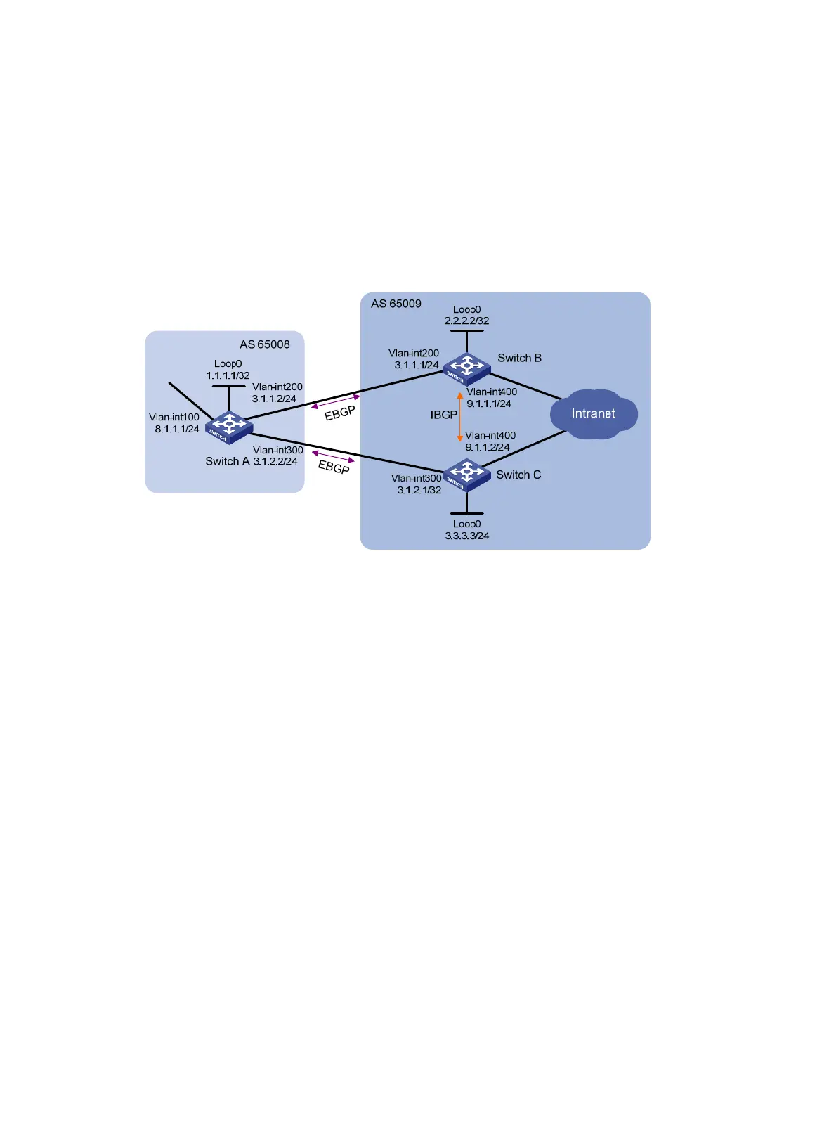
As shown in Figure 66, run EBGP between Switch A and Switch B, and between Switch A and Switch
C. Run IBGP between Switch B and Switch C. Configure load balancing over the two EBGP links on
Switch A.
Figure 66 Network diagram
Requirements analysis
On Switch A:
• Establish EBGP connections with Switch B and Switch C.
• Configure BGP to advertise network 8.1.1.0/24 to Switch B and Switch C, so that Switch B and
Switch C can access the internal network connected to Switch A.
On Switch B:
• Establish an EBGP connection with Switch A and an IBGP connection with Switch C.
• Configure BGP to advertise network 9.1.1.0/24 to Switch A, so that Switch A can access the
intranet through Switch B.
• Configure a static route to interface loopback 0 on Switch C (or use a routing protocol like OSPF)
to establish the IBGP connection.
On Switch C:
• Establish an EBGP connection with Switch A and an IBGP connection with Switch B.
• Configure BGP to advertise network 9.1.1.0/24 to Switch A, so that Switch A can access the
intranet through Switch C.
• Configure a static route to interface loopback 0 on Switch B (or use another protocol like OSPF)
to establish the IBGP connection.
Configure load balancing on Switch A.
Configuration procedure
1. Configure IP addresses for interfaces. (Details not shown.)
2. Configure BGP connections:

 Loading...


