317
# Configure the IP address of VLAN-interface 20.
[SwitchC] interface vlan-interface 20
[SwitchC-Vlan-interface20] ip address 1.1.3.2 24
Verifying the configuration
# Telnet to Switch B on Switch A. The operation succeeds.
# Telnet to Switch C on Switch A. The operation fails.
# Ping Switch C from Switch A. The operation succeeds.
Telnet uses TCP and ping uses ICMP. The results show the following:
• All TCP packets sent from Switch A are forwarded to the next hop 1.1.2.2.
• Other packets are forwarded through VLAN-interface 20.
• The local PBR configuration is effective.
Packet type-based interface PBR configuration example
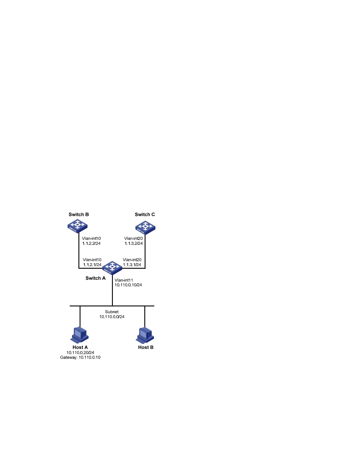
Network requirements
As shown in Figure 81, configure PBR on Switch A to forward all TCP packets received on
VLAN-interface 11 to the next hop 1.1.2.2. Switch A forwards other packets according to the routing
table.
Figure 81 Network diagram
Configuration procedure
1. Configure Switch A:
# Create VLAN 10 and VLAN 20.
<SwitchA> system-view
[SwitchA] vlan 10
[SwitchA-vlan10] quit
[SwitchA] vlan 20

 Loading...


