287
BGP FRR configuration example
Network requirements
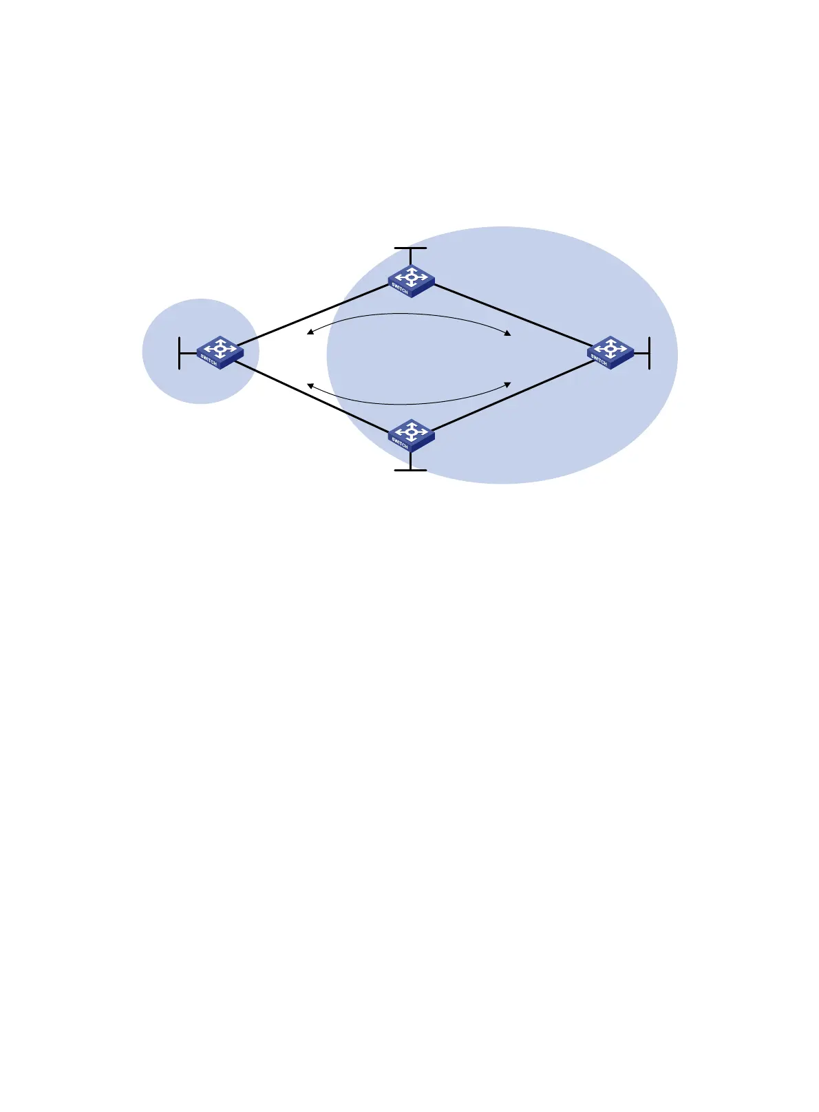
As shown in Figure 73, configure BGP FRR so that when Link B fails, BGP uses Link A to forward
traffic.
Figure 73 Network diagram
Configuration procedure
1. Configure IP addresses for interfaces. (Details not shown.)
2. Configure OSPF in AS 200 to ensure connectivity among Switch B, Switch C and Switch D.
(Details not shown.)
3. Configure BGP connections:
# Configure Switch A to establish EBGP sessions with Switch B and Switch C, and advertise
network 1.1.1.1/32.
<SwitchA> system-view
[SwitchA] bgp 100
[SwitchA-bgp] router-id 1.1.1.1
[SwitchA-bgp] peer 10.1.1.2 as-number 200
[SwitchA-bgp] peer 30.1.1.3 as-number 200
[SwitchA-bgp] address-family ipv4 unicast
[SwitchA-bgp-ipv4] peer 10.1.1.2 enable
[SwitchA-bgp-ipv4] peer 30.1.1.3 enable
[SwitchA-bgp-ipv4] network 1.1.1.1 32
# Configure Switch B to establish an EBGP session with Switch A, and an IBGP session with
Switch D.
<SwitchB> system-view
[SwitchB] bgp 200
[SwitchB-bgp] router-id 2.2.2.2
[SwitchB-bgp] peer 10.1.1.1 as-number 100
[SwitchB-bgp] peer 4.4.4.4 as-number 200
[SwitchB-bgp] peer 4.4.4.4 connect-interface loopback 0
[SwitchB-bgp] address-family ipv4 unicast
[SwitchB-bgp-ipv4] peer 10.1.1.1 enable
Switch B
Switch C
Switch D
AS 200
AS 100
Switch A
Loop0
1.1.1.1/32
Loop0
4.4.4.4/32
Vlan-int 200
30.1.1.1/24
Vlan-int 100
10.1.1.1/24
Vlan-int 100
10.1.1.2/24
Vlan-int 101
20.1.1.2/24
Vlan-int 201
40.1.1.4/24
Vlan-int 101
20.1.1.4/24
Vlan-int 200
30.1.1.3/24
Vlan-int 201
40.1.1.3/24
Link A
Link B
Loop0
2.2.2.2/32
Loop0
3.3.3.3/32

 Loading...


