57
NibID: 0x12000002 LastAs: 0
AttrID: 0xffffffff Neighbor: 192.168.2.2
Flags: 0x1008c OrigNextHop: 192.168.2.2
Label: NULL RealNextHop: 192.168.1.2
BkLabel: NULL BkNextHop: N/A
Tunnel ID: Invalid Interface: vlan-interface 100
BkTunnel ID: Invalid BkInterface: N/A
# Display RIP routes destined for 100.1.1.0/24 on Switch A when the link between Switch B and
Switch C fails.
<SwitchA> display ip routing-table 100.1.1.0 24 verbose
Summary Count : 1
Destination: 100.1.1.0/24
Protocol: RIP Process ID: 2
SubProtID: 0x1 Age: 00h18m40s
Cost: 2 Preference: 100
Tag: 0 State: Active Adv
OrigTblID: 0x0 OrigVrf: default-vrf
TableID: 0x2 OrigAs: 0
NibID: 0x12000003 LastAs: 0
AttrID: 0xffffffff Neighbor: 192.168.3.2
Flags: 0x1008c OrigNextHop: 192.168.3.2
Label: NULL RealNextHop: 192.168.3.2
BkLabel: NULL BkNextHop: N/A
Tunnel ID: Invalid Interface: vlan-interface 300
BkTunnel ID: Invalid BkInterface: N/A
RIP FRR configuration example
Network requirements
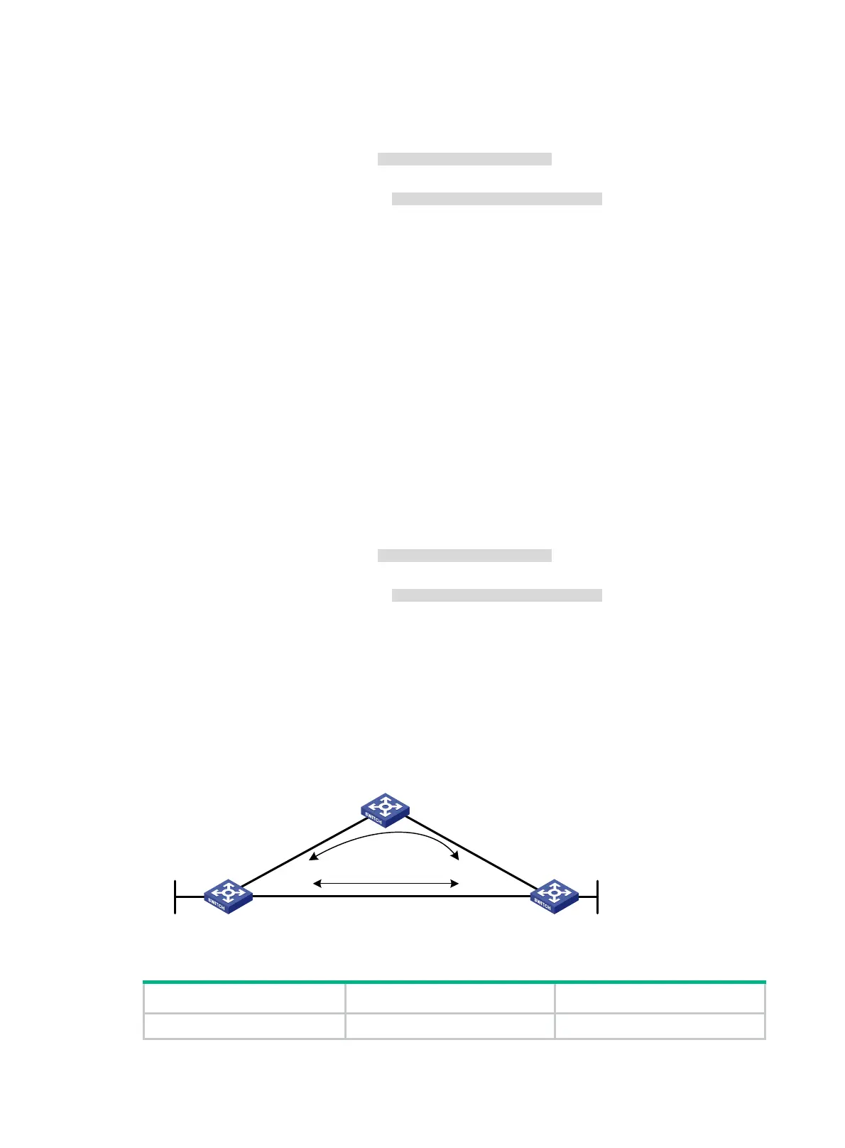
As shown in Figure 14, Switch A, Switch B, and Switch C run RIPv2. Configure RIP FRR so that
when Link A becomes unidirectional, services can be switched to Link B immediately.
Figure 14 Network diagram
Table 8 Interface and IP address assignment
Device Interface IP address
Switch A VLAN-interface 100 12.12.12.1/24
Switch A Switch B
Switch C
Loop0
V
l
a
n
-
i
n
t
1
0
0
Vlan-int200
Vlan-int200
V
l
a
n
-
i
n
t
1
0
0
V
l
a
n
-
i
n
t
1
0
1
V
l
a
n
-
i
n
t
1
0
1
Loop0
Link A
Link B

 Loading...


