20
Static route FRR configuration example
Network requirements
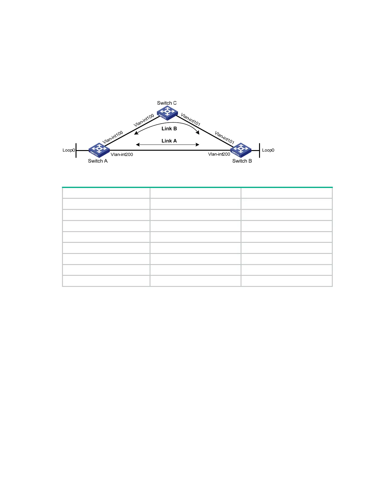
As shown in Figure 5, configure static routes on Switch A, Switch B, and Switch C, and configure
static route FRR. When Link A becomes unidirectional, traffic can be switched to Link B immediately.
Figure 5 Network diagram
Table 6 Interface and IP address assignment
Device Interface IP address
Switch A VLAN-interface 100 12.12.12.1/24
Switch A VLAN-interface 200 13.13.13.1/24
Switch A Loopback 0 1.1.1.1/32
Switch B VLAN-interface 101 24.24.24.4/24
Switch B VLAN-interface 202 13.13.13.2/24
Switch B Loopback 0 4.4.4.4/32
Switch C VLAN-interface 100 12.12.12.2/24
Switch C VLAN-interface 101 24.24.24.2/24
Configuration procedure
1. Configure IP addresses for interfaces. (Details not shown.)
2. Configure static route FRR on link A by using one of the following methods:
{ (Method 1.) Specify a backup next hop for static route FRR:
# Configure a static route on Switch A, and specify VLAN-interface 100 as the backup
output interface and 12.12.12.2 as the backup next hop.
<SwitchA> system-view
[SwitchA] bfd echo-source-ip 2.2.2.2
[SwitchA] ip route-static 4.4.4.4 32 vlan-interface 200 13.13.13.2
backup-interface vlan-interface 100 backup-nexthop 12.12.12.2
# Configure a static route on Switch B, and specify VLAN-interface 101 as the backup
output interface and 24.24.24.2 as the backup next hop.
<SwitchB> system-view
[SwitchB] bfd echo-source-ip 3.3.3.3
[SwitchB] ip route-static 1.1.1.1 32 vlan-interface 200 13.13.13.1
backup-interface vlan-interface 101 backup-nexthop 24.24.24.2
{ (Method 2.) Configure static route FRR to automatically select a backup next hop:
# Configure static routes on Switch A, and enable static route FRR.
<SwitchA> system-view
 Loading...


