114
OSPF GR configuration example
Network requirements
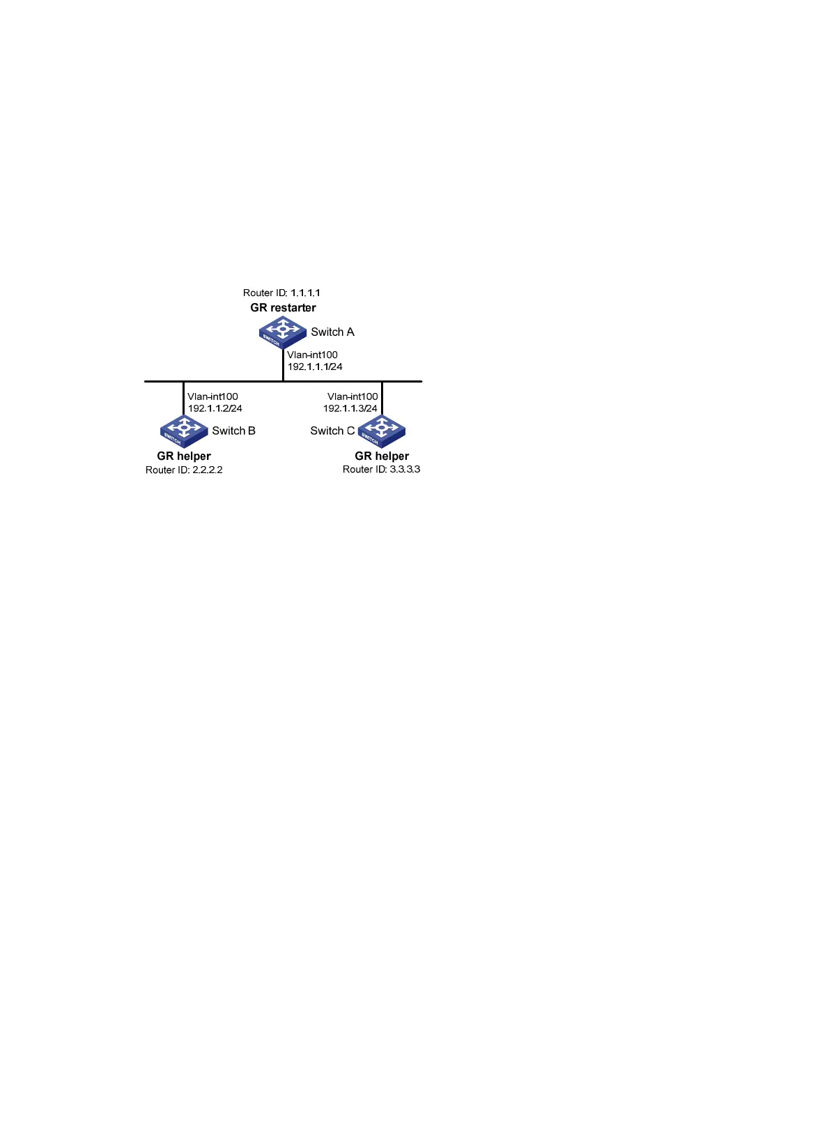
As shown in Figure 29:
• Switch A, Switch B, and Switch C that belong to the same AS and the same OSPF routing
domain are GR capable.
• Switch A acts as the non-IETF GR restarter. Switch B and Switch C are the GR helpers, and
synchronize their LSDBs with Switch A through OOB communication of GR.
Figure 29 Network diagram
Configuration procedure
1. Configure IP addresses for interfaces. (Details not shown.)
2. Enable OSPF:
# Configure Switch A.
SwitchA> system-view
[SwitchA] router id 1.1.1.1
[SwitchA] ospf 100
[SwitchA-ospf-100] area 0
[SwitchA-ospf-100-area-0.0.0.0] network 192.1.1.0 0.0.0.255
[SwitchA-ospf-100-area-0.0.0.0] quit
# Configure Switch B.
<SwitchB> system-view
[SwitchB] router id 2.2.2.2
[SwitchB] ospf 100
[SwitchB-ospf-100] area 0
[SwitchB-ospf-100-area-0.0.0.0] network 192.1.1.0 0.0.0.255
[SwitchB-ospf-100-area-0.0.0.0] quit
# Configure Switch C.
<SwitchC> system-view
[SwitchC] router id 3.3.3.3
[SwitchC] ospf 100
[SwitchC-ospf-100] area 0
[SwitchC-ospf-100-area-0.0.0.0] network 192.1.1.0 0.0.0.255
[SwitchC-ospf-100-area-0.0.0.0] quit
3. Configure OSPF GR:

 Loading...


