175
Destination: 120.1.1.0/24
Protocol: ISIS Process ID: 1
SubProtID: 0x1 Age: 04h20m37s
Cost: 20 Preference: 10
Tag: 0 State: Active Adv
OrigTblID: 0x0 OrigVrf: default-vrf
TableID: 0x2 OrigAs: 0
NibID: 0x26000002 LastAs: 0
AttrID: 0xffffffff Neighbor: 0.0.0.0
Flags: 0x1008c OrigNextHop: 10.1.1.100
Label: NULL RealNextHop: 10.1.1.100
BkLabel: NULL BkNextHop: N/A
Tunnel ID: Invalid Interface: Vlan-interface11
BkTunnel ID: Invalid BkInterface: N/A
The output shows that Switch A and Switch B communicate through VLAN-interface 11.
IS-IS FRR configuration example
Network requirements
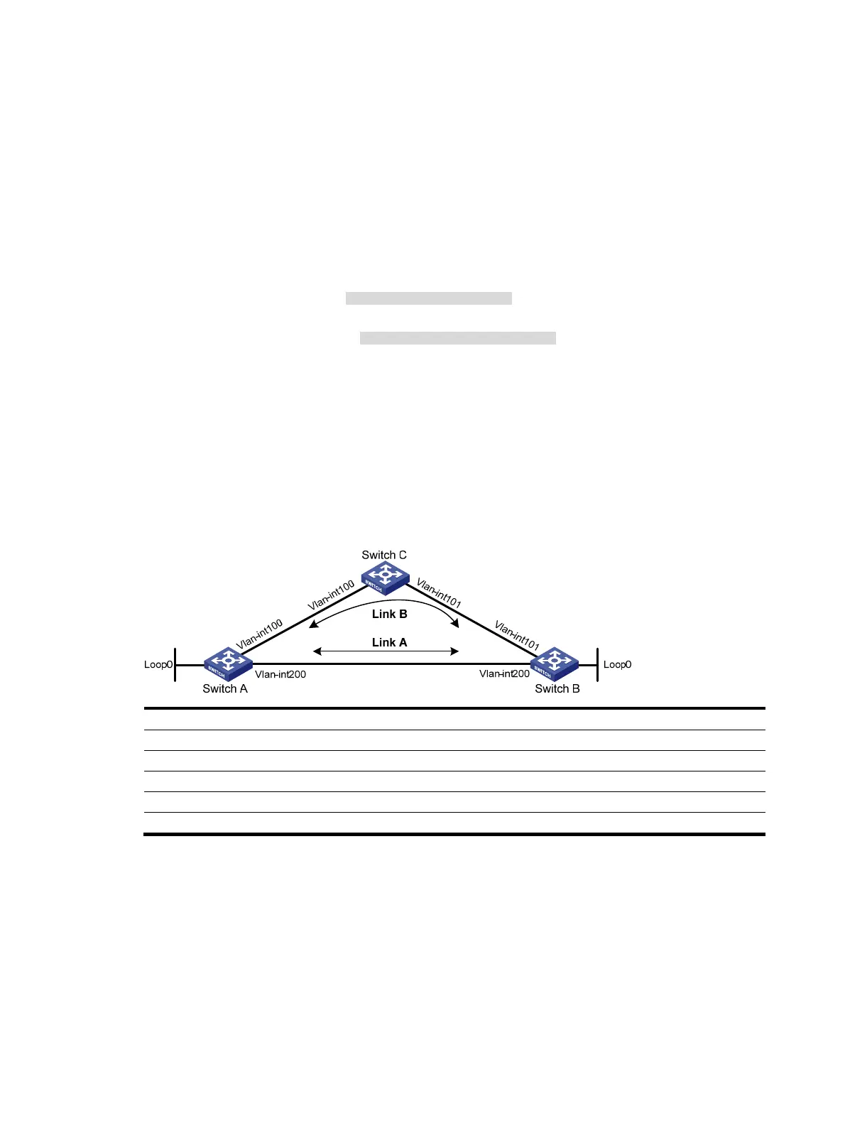
As shown in Figure 47, Switch A, Switch B, and Switch C belong to the same IS-IS routing domain.
Configure IS-IS FRR so that when the Link A fails, traffic can be switched to Link B immediately.
Figure 47 Network diagram
Device Interface IP address Device Interface IP address
Switch A Vlan-int100 12.12.12.1/24 Switch B Vlan-int101 24.24.24.4/24
Vlan-int200 13.13.13.1/24 Vlan-int200 13.13.13.2/24
Loop0 1.1.1.1/32 Loop0 4.4.4.4/32
Switch C Vlan-int100 12.12.12.2/24
Vlan-int101 24.24.24.2/24
Configuration procedure
1. Configure IP addresses and subnet masks for interfaces on the switches. (Details not shown.)
2. Configure IS-IS on the switches to make sure Switch A, Switch B, and Switch C can
communicate with each other at Layer 3. (Details not shown.)
3. Configure IS-IS FRR:
Enable IS-IS FRR to automatically calculate a backup next hop, or designate a backup next hop
by using a referenced routing policy.
{ (Method 1.) Enable IS-IS FRR to automatically calculate a backup next hop:
# Configure Switch A.
<SwitchA> system-view

 Loading...


