290
[SwitchD] display ip routing-table 1.1.1.1 32 verbose
Summary Count : 1
Destination: 1.1.1.1/32
Protocol: BGP Process ID: 0
SubProtID: 0x1 Age: 00h00m36s
Cost: 0 Preference: 255
IpPre: N/A QosLocalID: N/A
Tag: 0 State: Active Adv
OrigTblID: 0x0 OrigVrf: default-vrf
TableID: 0x2 OrigAs: 100
NibID: 0x15000003 LastAs: 100
AttrID: 0x1 Neighbor: 2.2.2.2
Flags: 0x10060 OrigNextHop: 2.2.2.2
Label: NULL RealNextHop: 20.1.1.2
BkLabel: NULL BkNextHop: 40.1.1.3
Tunnel ID: Invalid Interface: Vlan-interface 101
BkTunnel ID: Invalid BkInterface: Vlan-interface 201
FtnIndex: 0x0
IPv6 BGP configuration examples
IPv6 BGP basic configuration example
Network requirements
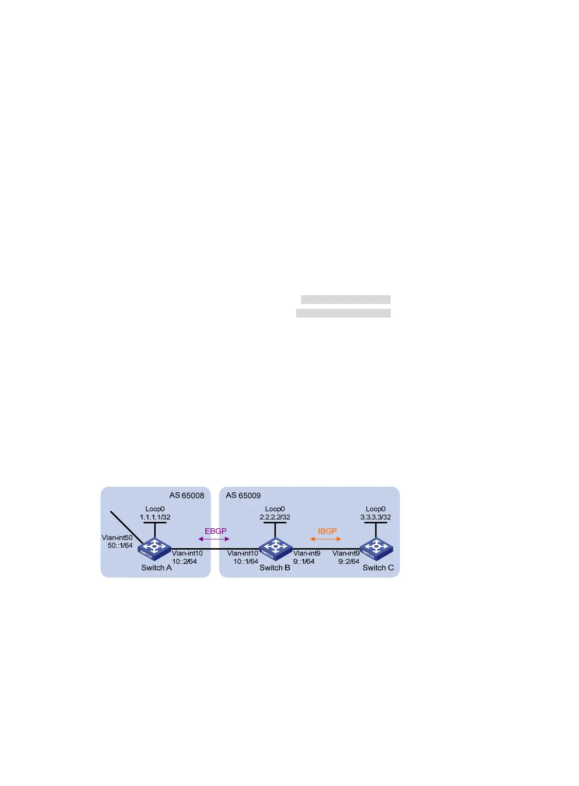
As shown in Figure 74, all switches run BGP. Run EBGP between Switch A and Switch B, and run
IBGP between Switch B and Switch C to allow Switch C to access network 50::/64 connected to
Switch A.
Figure 74 Network diagram
Configuration procedure
1. Configure IP addresses for interfaces. (Details not shown.)
2. Configure IBGP:
# Configure Switch B.
<SwitchB> system-view
[SwitchB] bgp 65009
[SwitchB-bgp] router-id 2.2.2.2
[SwitchB-bgp] peer 9::2 as-number 65009
[SwitchB-bgp] address-family ipv6

 Loading...


