158
IPv4 Destination IntCost ExtCost ExitInterface NextHop Flags
-------------------------------------------------------------------------------
192.168.0.0/24 10 NULL Vlan300 Direct D/L/-
10.1.1.0/24 20 NULL Vlan300 192.168.0.1 R/-/-
10.1.2.0/24 20 NULL Vlan300 192.168.0.1 R/-/-
172.16.0.0/16 10 NULL Vlan100 Direct D/L/-
Flags: D-Direct, R-Added to Rib, L-Advertised in LSPs, U-Up/Down Bit Set
The output shows that the routing table of Level-1 switches contains a default route with the next hop
as the Level-1-2 switch. The routing table of Level-2 switch contains both routing information of
Level-1 and Level-2.
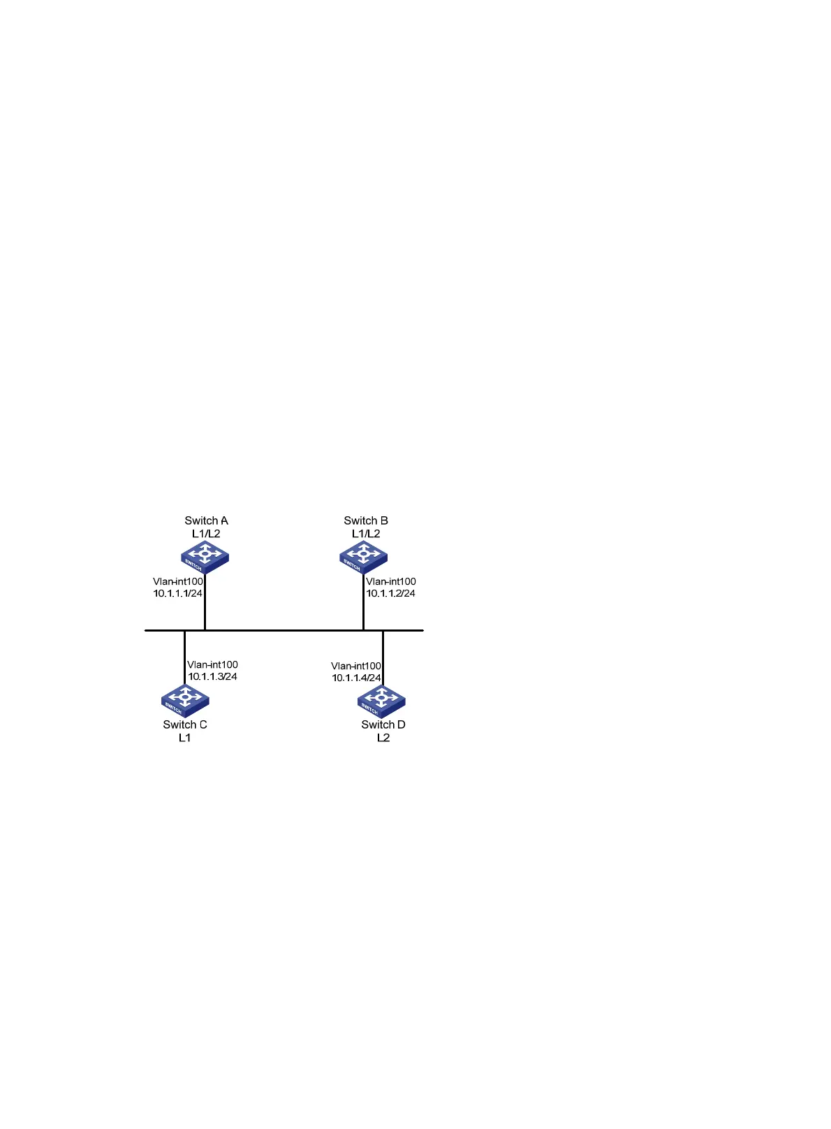
DIS election configuration example
Network requirements
As shown in Figure 41, Switches A, B, C, and D reside in IS-IS area 10 on a broadcast network
(Ethernet). Switch A and Switch B are Level-1-2 switches, Switch C is a Level-1 switch, and Switch D
is a Level-2 switch.
Change the DIS priority of Switch A to make it elected as the Level-1-2 DIS router.
Figure 41 Network diagram
Configuration procedure
1. Configure IP addresses for interfaces. (Details not shown.)
2. Enable IS-IS:
# Configure Switch A.
<SwitchA> system-view
[SwitchA] isis 1
[SwitchA-isis-1] network-entity 10.0000.0000.0001.00
[SwitchA-isis-1] quit
[SwitchA] interface vlan-interface 100
[SwitchA-Vlan-interface100] isis enable 1
[SwitchA-Vlan-interface100] quit
# Configure Switch B.
<SwitchB> system-view

 Loading...


