172
14.14.14.0/24 10 NULL vlan200 Direct D/L/-
44.44.44.44/32 10 NULL Loop0 Direct D/-/-
12.12.12.0/32 10 NULL vlan200 14.14.14.4 R/L/-
22.22.22.22/32 10 NULL vlan200 14.14.14.4 R/L/-
Flags: D-Direct, R-Added to Rib, L-Advertised in LSPs, U-Up/Down Bit Set
Level-2 IPv4 Forwarding Table
-----------------------------
IPv4 Destination IntCost ExtCost ExitInterface NextHop Flags
-------------------------------------------------------------------------------
14.14.14.0/24 10 NULL vlan200 Direct D/L/-
44.44.44.44/32 10 NULL Loop0 Direct D/-/-
12.12.12.0/32 10 NULL
22.22.22.22/32 10 NULL
Flags: D-Direct, R-Added to Rib, L-Advertised in LSPs, U-Up/Down Bit Set
The output shows that the neighbor information and routing information on Switch A and Switch B
have not changed during the active/standby switchover on Switch S. The neighbors are unaware of
the switchover.
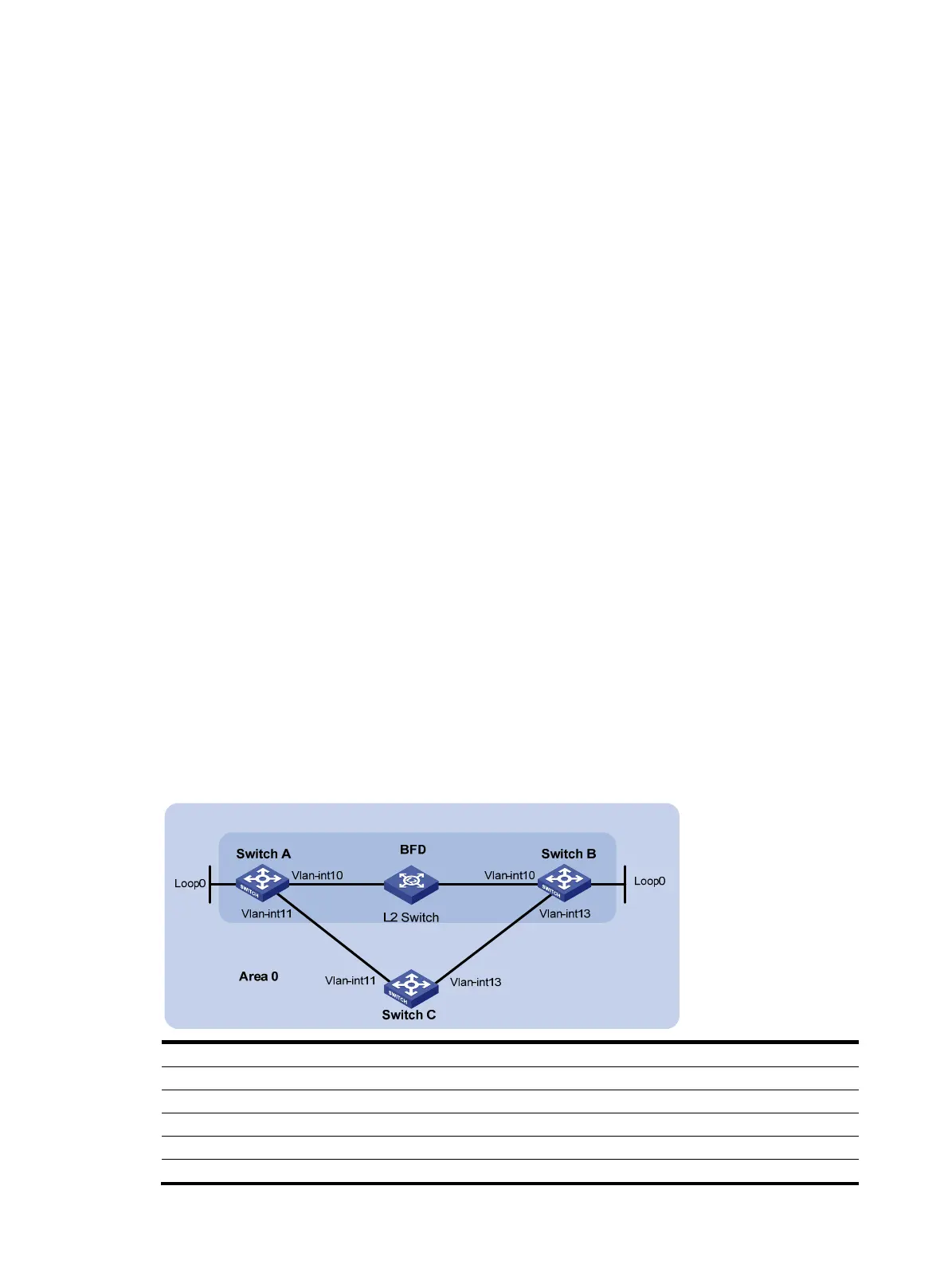
BFD for IS-IS configuration example
Network requirements
• As shown in Figure 46, run IS-IS on Switch A, Switch B and Switch C so that can reach each
other at the network layer.
• After the link over which Switch A and Switch B communicate through the Layer-2 switch fails,
BFD can quickly detect the failure and notify IS-IS of the failure. Switch A and Switch B then
communicate through Switch C.
Figure 46 Network diagram
Device Interface IP address Device Interface IP address
Switch A Vlan-int10 10.1.0.102/24 Switch B Vlan-int10 10.1.0.100/24
Vlan-int11 11.1.1.1/24 Vlan-int13 13.1.1.1/24
Loop0 121.1.1.1/32 Loop0 120.1.1.1/32
Switch C Vlan-int11 11.1.1.2/24
Vlan-int13 13.1.1.2/24

 Loading...


