15
Trace complete.
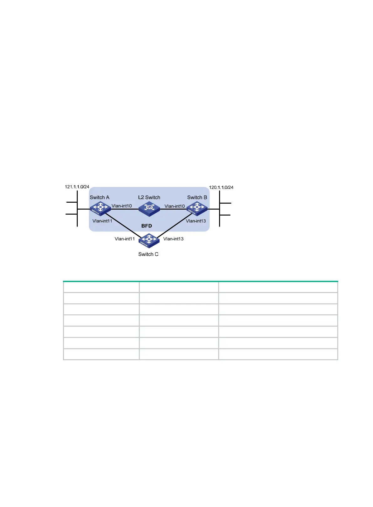
BFD for static routes configuration example (direct next hop)
Network requirements
Configure the following, as shown in Figure 3:
• Configure a static route to subnet 120.1.1.0/24 on Switch A.
• Configure a static route to subnet 121.1.1.0/24 on Switch B.
• Enable BFD for both routes.
• Configure a static route to subnet 120.1.1.0/24 and a static route to subnet 121.1.1.0/24 on
Switch C.
When the link between Switch A and Switch B through the Layer 2 switch fails, BFD can detect the
failure immediately. Switch A then communicates with Switch B through Switch C.
Figure 3 Network diagram
Table 4 Interface and IP address assignment
Device Interface IP address
Switch A VLAN-interface 10 12.1.1.1/24
Switch A VLAN-interface 11 10.1.1.102/24
Switch B VLAN-interface 10 12.1.1.2/24
Switch B VLAN-interface 13 13.1.1.1/24
Switch C VLAN-interface 11 10.1.1.100/24
Switch C VLAN-interface 13 13.1.1.2/24
Configuration procedure
1. Configure IP addresses for the interfaces. (Details not shown.)
2. Configure static routes and BFD:
# Configure static routes on Switch A and enable BFD control mode for the static route that
traverses the Layer 2 switch.
<SwitchA> system-view
[SwitchA] interface vlan-interface 10
[SwitchA-vlan-interface10] bfd min-transmit-interval 500
[SwitchA-vlan-interface10] bfd min-receive-interval 500
[SwitchA-vlan-interface10] bfd detect-multiplier 9
[SwitchA-vlan-interface10] quit

 Loading...


