283
[SwitchB-bgp-ipv4] peer 200.1.1.2 enable
[SwitchB-bgp-ipv4] peer 9.1.1.2 enable
3. Configure Switch C:
# Configure IP addresses for interfaces. (Details not shown.)
# Configure the IBGP connection.
<SwitchC> system-view
[SwitchC] bgp 65009
[SwitchC-bgp] router-id 3.3.3.3
[SwitchC-bgp] peer 9.1.1.1 as-number 65009
# Enable GR capability for BGP.
[SwitchC-bgp] graceful-restart
# Enable Switch C to exchange IPv4 unicast routing information with Switch B.
[SwitchC-bgp-ipv4] peer 9.1.1.1 enable
Verifying the configuration
Ping Switch C on Switch A. Meanwhile, perform an active/standby switchover on Switch B. The ping
operation is successful during the whole switchover process.
BFD for BGP configuration example
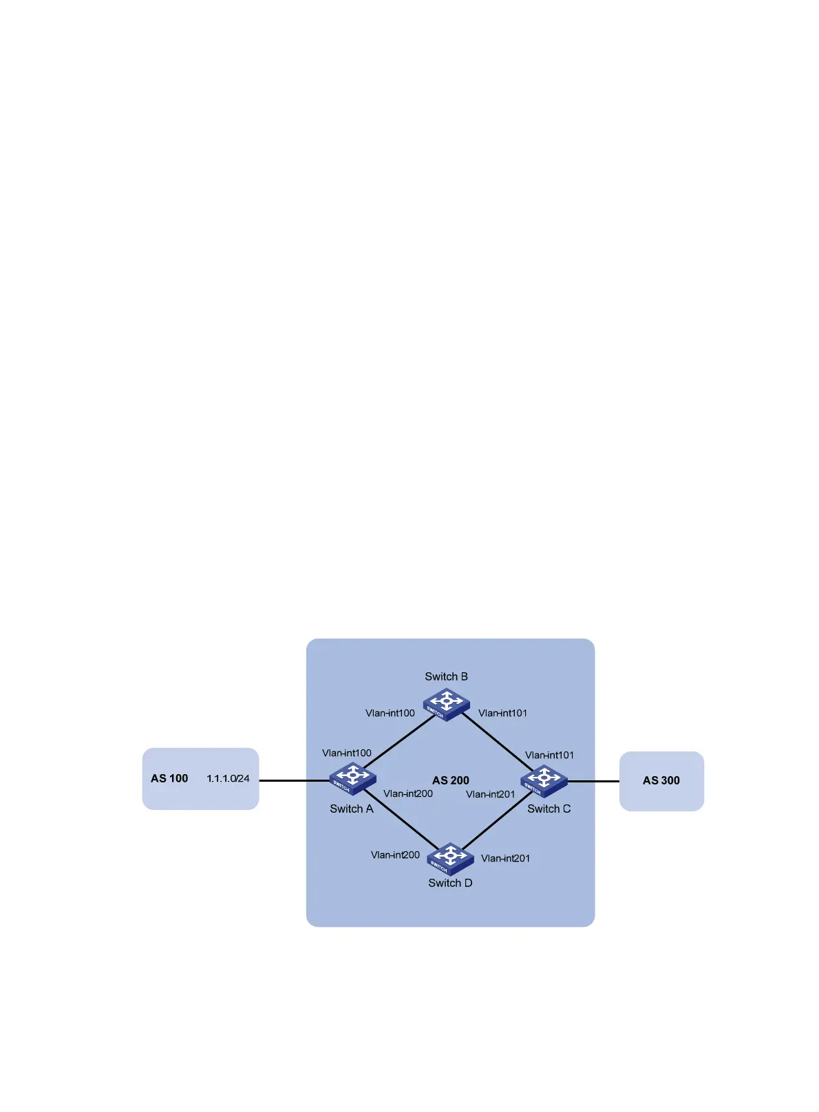
Network requirements
As shown in Figure 72, configure OSPF as the IGP in AS 200.
• Establish two IBGP connections between Switch A and Switch C. When both paths operate
correctly, Switch C uses the path Switch A<—>Switch B<—>Switch C to exchange packets
with network 1.1.1.0/24.
• Configure BFD over the path. When the path fails, BFD can quickly detect the failure and notify
it to BGP. Then, the path Switch A<—>Switch D<—>Switch C takes effect immediately.
Figure 72 Network diagram

 Loading...


