49
127.0.0.0/32 Direct 0 0 127.0.0.1 InLoop0
127.0.0.1/32 Direct 0 0 127.0.0.1 InLoop0
127.255.255.255/32 Direct 0 0 127.0.0.1 InLoop0
BFD for RIP configuration example (single-hop echo
detection for a directly connected neighbor)
Network requirements
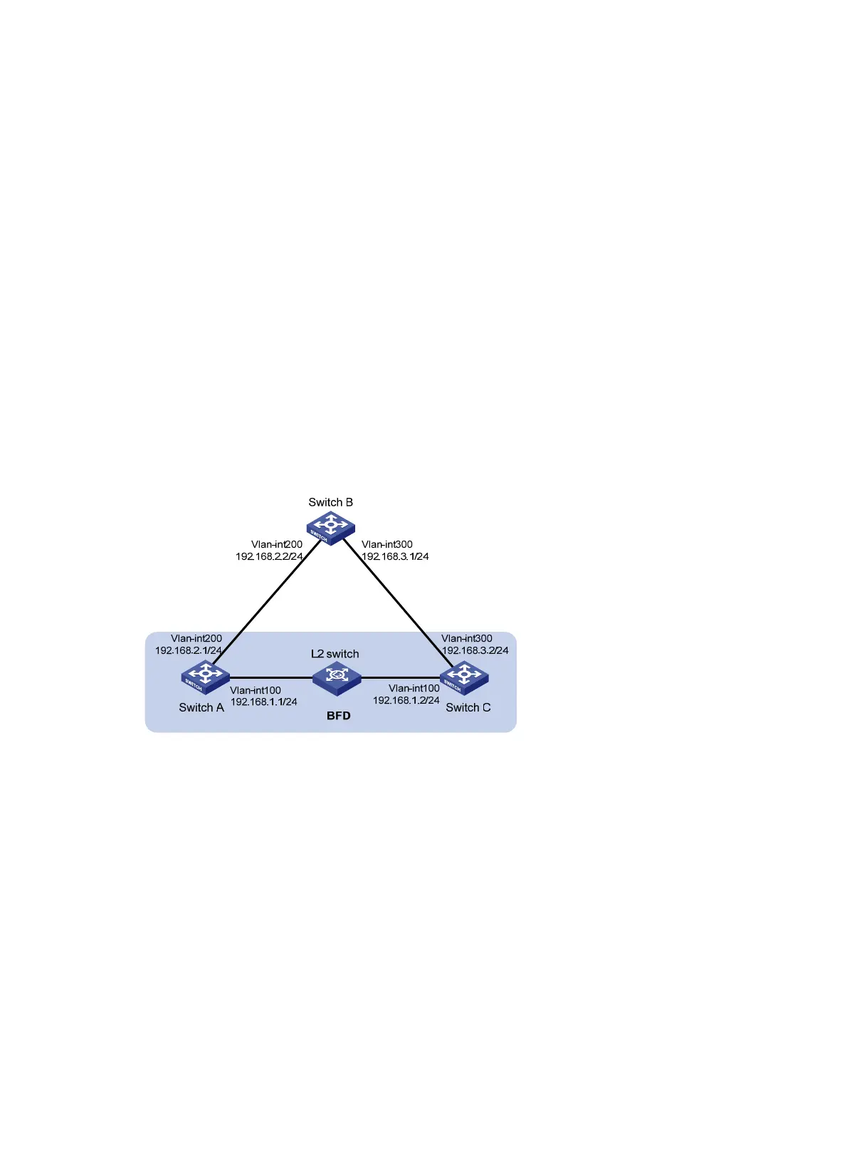
As shown in Figure 11, VLAN-interface 100 of Switch A and Switch C runs RIP process 1.
VLAN-interface 200 of Switch A runs RIP process 2. VLAN-interface 300 of Switch C and
VLAN-interface 200 and VLAN-interface 300 of Switch B run RIP process 1.
• Configure a static route destined for 100.1.1.1/24 and enable static route redistribution into RIP
on Switch C. This allows Switch A to learn two routes destined for 100.1.1.1/24 through
VLAN-interface 100 and VLAN-interface 200 respectively, and uses the one through
VLAN-interface 100.
• Enable BFD for RIP on VLAN-interface 100 of Switch A. When the link over VLAN-interface 100
fails, BFD can quickly detect the failure and notify it to RIP. RIP deletes the neighbor
relationship and route information learned on VLAN-interface 100. It uses the route destined for
100.1.1.1 24 through VLAN-interface 200.
Figure 11 Network diagram
Configuration procedure
1. Configure IP addresses for interfaces. (Details not shown.)
2. Configure basic RIP:
# Configure Switch A.
<SwitchA> system-view
[SwitchA] rip 1
[SwitchA-rip-1] version 2
[SwitchA-rip-1] undo summary
[SwitchA-rip-1] network 192.168.1.0
[SwitchA-rip-1] quit
[SwitchA] interface vlan-interface 100
[SwitchA-Vlan-interface100] rip bfd enable
[SwitchA-Vlan-interface100] quit
[SwitchA] rip 2

 Loading...


