387
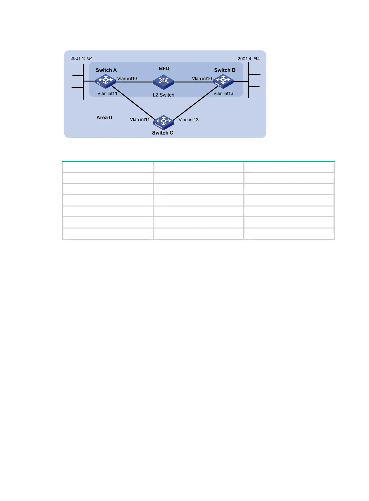
Figure 95 Network diagram
Table 21 Interface and IP address assignment
Device Interface IPv6 address
Switch A
Vlan-int10
2001::1/64
Switch A
Vlan-int11
2001:2::1/64
Switch B
Vlan-int10
2001::2/64
Switch B Vlan-int13 2001:3::2/64
Switch C Vlan-int11 2001:2::2/64
Switch C Vlan-int13 2001:3::1/64
Configuration procedure
1. Configure IPv6 addresses for the interfaces. (Details not shown.)
2. Configure basic OSPFv3:
# On Switch A, enable OSPFv3 and specify the router ID as 1.1.1.1.
<SwitchA> system-view
[SwitchA] ospfv3
[SwitchA-ospfv3-1] router-id 1.1.1.1
[SwitchA-ospfv3-1] quit
[SwitchA] interface vlan-interface 10
[SwitchA-Vlan-interface10] ospfv3 1 area 0
[SwitchA-Vlan-interface10] quit
[SwitchA] interface vlan-interface 11
[SwitchA-Vlan-interface11] ospfv3 1 area 0
[SwitchA-Vlan-interface11] quit
# On Switch B, enable OSPFv3 and specify the router ID as 2.2.2.2.
<SwitchB> system-view
[SwitchB] ospfv3
[SwitchB-ospfv3-1] router-id 2.2.2.2
[SwitchB-ospfv3-1] quit
[SwitchB] interface vlan-interface 10
[SwitchB-Vlan-interface10] ospfv3 1 area 0
[SwitchB-Vlan-interface10] quit
[SwitchB] interface vlan-interface 13
[SwitchB-Vlan-interface13] ospfv3 1 area 0

 Loading...


