54
NibID: 0x12000002 LastAs: 0
AttrID: 0xffffffff Neighbor: 192.168.3.2
Flags: 0x1008c OrigNextHop: 192.168.3.2
Label: NULL RealNextHop: 192.168.3.2
BkLabel: NULL BkNextHop: N/A
Tunnel ID: Invalid Interface: vlan-interface 200
BkTunnel ID: Invalid BkInterface: N/A
BFD for RIP configuration example (bidirectional detection in
BFD control packet mode)
Network requirements
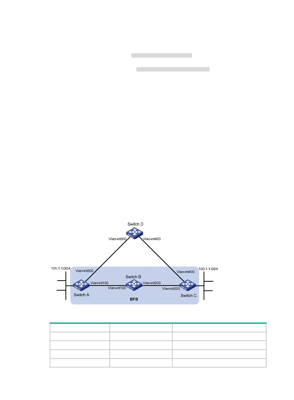
As shown in Figure 13, VLAN-interface 100 of Switch A and VLAN-interface 200 of Switch C run RIP
process 1.
VLAN-interface 300 of Switch A runs RIP process 2. VLAN-interface 400 of Switch C, and
VLAN-interface 300 and VLAN-interface 400 of Switch D run RIP process 1.
• Configure a static route destined for 100.1.1.0/24 on Switch A.
• Configure a static route destined for 101.1.1.0/24 on Switch C.
• Enable static route redistribution into RIP on Switch A and Switch C. This allows Switch A to
learn two routes destined for 100.1.1.0/24 through VLAN-interface 100 and VLAN-interface 300.
It uses the route through VLAN-interface 100.
• Enable BFD on VLAN-interface 100 of Switch A and VLAN-interface 200 of Switch C.
When the link over VLAN-interface 100 fails, BFD can quickly detect the link failure and notify RIP.
RIP deletes the neighbor relationship and the route information received learned on VLAN-interface
100. It uses the route destined for 100.1.1.0/24 through VLAN-interface 300.
Figure 13 Network diagram
Table 7 Interface and IP address assignment
Device Interface IP address
Switch A VLAN-interface 300 192.168.3.1/24
Switch A VLAN-interface 100 192.168.1.1/24
Switch B VLAN-interface 100 192.168.1.2/24
Switch B VLAN-interface 200 192.168.2.1/24

 Loading...


