375
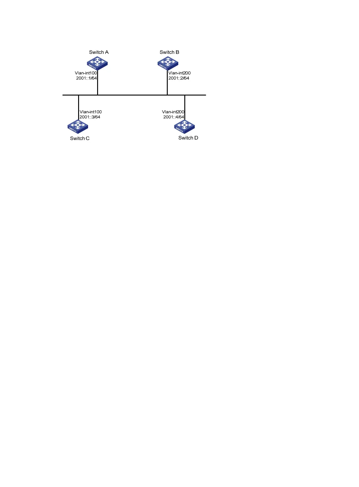
Figure 90 Network diagram
Configuration procedure
1. Configure IPv6 addresses for interfaces. (Details not shown.)
2. Configure basic OSPFv3:
# On Switch A, enable OSPFv3 and specify the router ID as 1.1.1.1.
<SwitchA> system-view
[SwitchA] ospfv3
[SwitchA-ospfv3-1] router-id 1.1.1.1
[SwitchA-ospfv3-1] quit
[SwitchA] interface vlan-interface 100
[SwitchA-Vlan-interface100] ospfv3 1 area 0
[SwitchA-Vlan-interface100] quit
# On Switch B, enable OSPFv3 and specify the router ID as 2.2.2.2.
<SwitchB> system-view
[SwitchB] ospfv3
[SwitchB-ospfv3-1] router-id 2.2.2.2
[SwitchB-ospfv3-1] quit
[SwitchB] interface vlan-interface 200
[SwitchB-Vlan-interface200] ospfv3 1 area 0
[SwitchB-Vlan-interface200] quit
# On Switch C, enable OSPFv3 and specify the router ID as 3.3.3.3.
<SwitchC> system-view
[SwitchC] ospfv3
[SwitchC-ospfv3-1] router-id 3.3.3.3
[SwitchC-ospfv3-1] quit
[SwitchC] interface vlan-interface 100
[SwitchC-Vlan-interface100] ospfv3 1 area 0
[SwitchC-Vlan-interface100] quit
# On Switch D, enable OSPFv3 and specify the router ID as 4.4.4.4.
<SwitchD> system-view
[SwitchD] ospfv3
[SwitchD-ospfv3-1] router-id 4.4.4.4
[SwitchD-ospfv3-1] quit
[SwitchD] interface vlan-interface 200
[SwitchD-Vlan-interface200] ospfv3 1 area 0

 Loading...


