Powermax125 Service Manual 808070 119
8 – Troubleshooting and System Tests
Indicator LEDs and device tests
The Hypertherm IGBT tester requires a minimum of 8 V to power its circuitry properly.
IGBT test preparation
Before testing with the Hypertherm IGBT tester, connect the colored leads to the IGBT as shown in Figure 8 and
Figure 9.
Before an IGBT can be tested, it must be electrically isolated from all circuits. If the IGBT
is installed in a power supply, remove the power board and any lead connections before
testing. (See Remove the power board on page 205.)
Figure 8 and Figure 9 depict 3 common configurations of an IGBT. Each connection on the IGBT will be labeled with an
abbreviation.
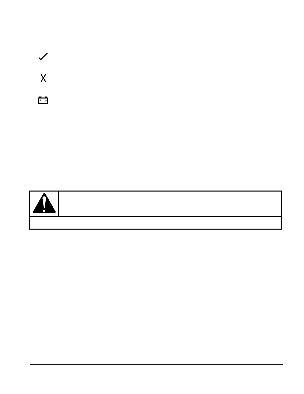
Green “pass” LED
When illuminated, this LED indicates that the IGBT passed the test for an open IGBT when the switch is
pressed to the right or for a short-circuited IGBT when the switch is pressed to the left.
Red “fail” LED
When illuminated, this LED indicates that the IGBT failed the test for an open IGBT when the switch is
pressed to the right or for a short-circuited IGBT when the switch is pressed to the left.
Red “low battery” LED
When illuminated, this LED indicates that the remaining voltage in the battery is insufficient to power the
test circuitry. Replace the battery.
CAUTION!
Failure to isolate the IGBT may result in false readings and/or damage to the IGBT tester.