EasyManuals Logo

Hypertherm Powermax 125 Service Manual

Hypertherm Powermax 125
317 pages
To Next Page IconTo Next Page
To Previous Page IconTo Previous Page
Page #238 background imageLoading...
Page #238 background image
238 Powermax125 Service Manual 808070
9 Power Supply Component Replacement
Replacing the output inductor
Remove the output inductor
1. Complete the following procedures:
a. See Disconnect the power and gas supply on page 166.
b. See Remove the power supply cover on page 172.
c. See Remove the component barrier on page 173.
d. See Remove the end panel bracket on page 174.
e. See Remove the fan shroud on page 216.
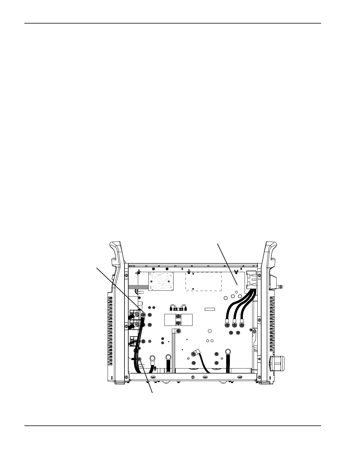
2. Remove the screw at J28 that secures the electrode wire to the power board.
3. Remove the screw securing the output inductor wires to the power board.
The power board in Figure 95 is a CSA model. The connections for the output inductor
wires and the electrode wire are the same for all models.
Figure 95
Kit number Description
428125 Kit: Powermax125 output inductor
J22 J21 J20 J19
J27
WORK
LEAD
J26
J25
+
_
+
_
RED
J18
ORG
J17
RED
J32
J11
B
R
J28
C152 C151
TP7
TP9
TP8
W
R
B
Output inductor wires mounting
screw
Electrode wire mounting screw (J28)
Power board

Table of Contents

Other manuals for Hypertherm Powermax 125

Questions and Answers:

Question and Answer IconNeed help?

Do you have a question about the Hypertherm Powermax 125 and is the answer not in the manual?

Hypertherm Powermax 125 Specifications

General IconGeneral
Output Current30-125 A
Input Power15.2 kW
Open Circuit Voltage300 VDC
Gas SupplyClean, dry, oil-free air or nitrogen
Input Power Cable Length10 ft (3 m)
Rated Output Current125 A
Gas TypeAir or nitrogen
Cutting Capacity1-1/4 inch (32 mm)
Pierce Capacity1 inch (25 mm)
Input Voltage200-600 V, 3-PH
Duty Cycle100% @ 125 A
CertificationsCSA
Maximum Clean Cut Thickness1-1/4 inch (32 mm)
Cooling MethodFan-cooled
Torch OptionsHand

Related product manuals