Powermax125 Service Manual 808070 149
8 – Troubleshooting and System Tests
System tests
Before performing any tests, complete the Internal inspection on page 115 and the resistance check in Test 2 – DC
power bus on page 152. These tests should only be performed by a qualified service technician. Wear the proper
personal protective equipment and use approved tools and measurement equipment.
Before purchasing a major replacement component, verify the problem with Hypertherm Technical Service or the nearest
Hypertherm repair facility.
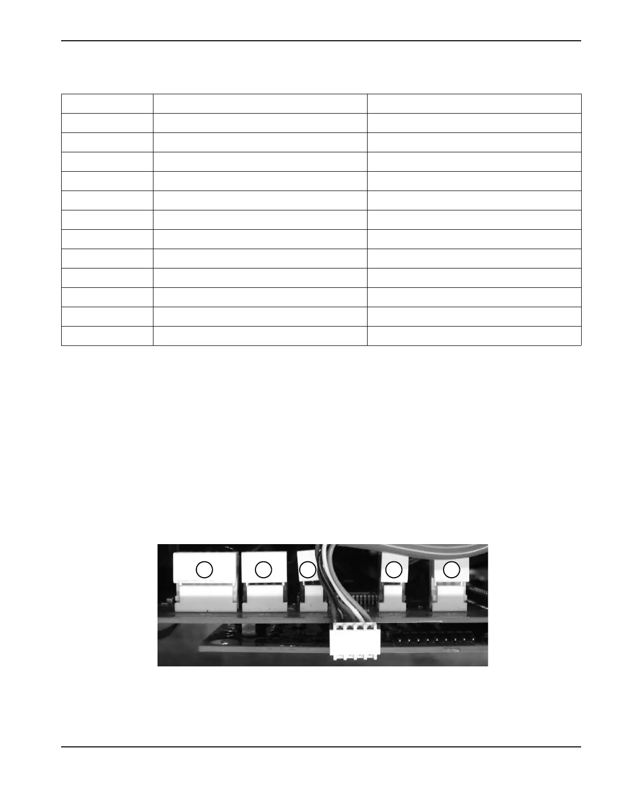
Several connectors require you to remove a white cap to access the test points. Figure 19 shows examples of
connectors located at the top of the power board. You can pry off most covers with your thumbnail. However, you may
need to use a small blade screwdriver to carefully pry off some of the covers. Be careful not to bend or break the
connectors.
Figure 19
Test number Description Associated fault codes
1 Voltage input 0-60-ALL
2DC power buss 3-43-0
3 Output diode bridge General
4 Temperature out of range 0-40-ALL, 2-10-ALL
5 Flyback (DC to DC) circuit 3-00-0, 3-42-ALL, 3-43-ALL
6 Torch stuck open/closed 0-30-ALL
7 Start signal General, 0-51-0
8 Torch cap-sensor switch 0-50-0
9 Electronic regulator 0-21-0, 3-20-ALL
10 Pressure sensor 0-12-0, 0-20-0, 2-11-ALL
11 Fan 3-10-ALL
12 Power switch auxiliary Unreported interlock at START
1 Electronic regulator (J6)
2 Pressure switch/auxiliary contactor (J5)
3 Pressure sensor (J3)
4 Inverter temperature sensor (J2)
5 Fan (J1)