132 Powermax125 Service Manual 808070
8 – Troubleshooting and System Tests
Fault code format – 0-nn-n
These fault codes identify operational faults. On the operator screen, the last digit is omitted. Display the service screen
for more information on faults 11, 19, 30, 40, 60, and 99.
Fault codes beginning with zero (0-nn-n) are not recorded in the fault log.
0-nn-n
Fault
code
Description
Power
LED
Fault
LED
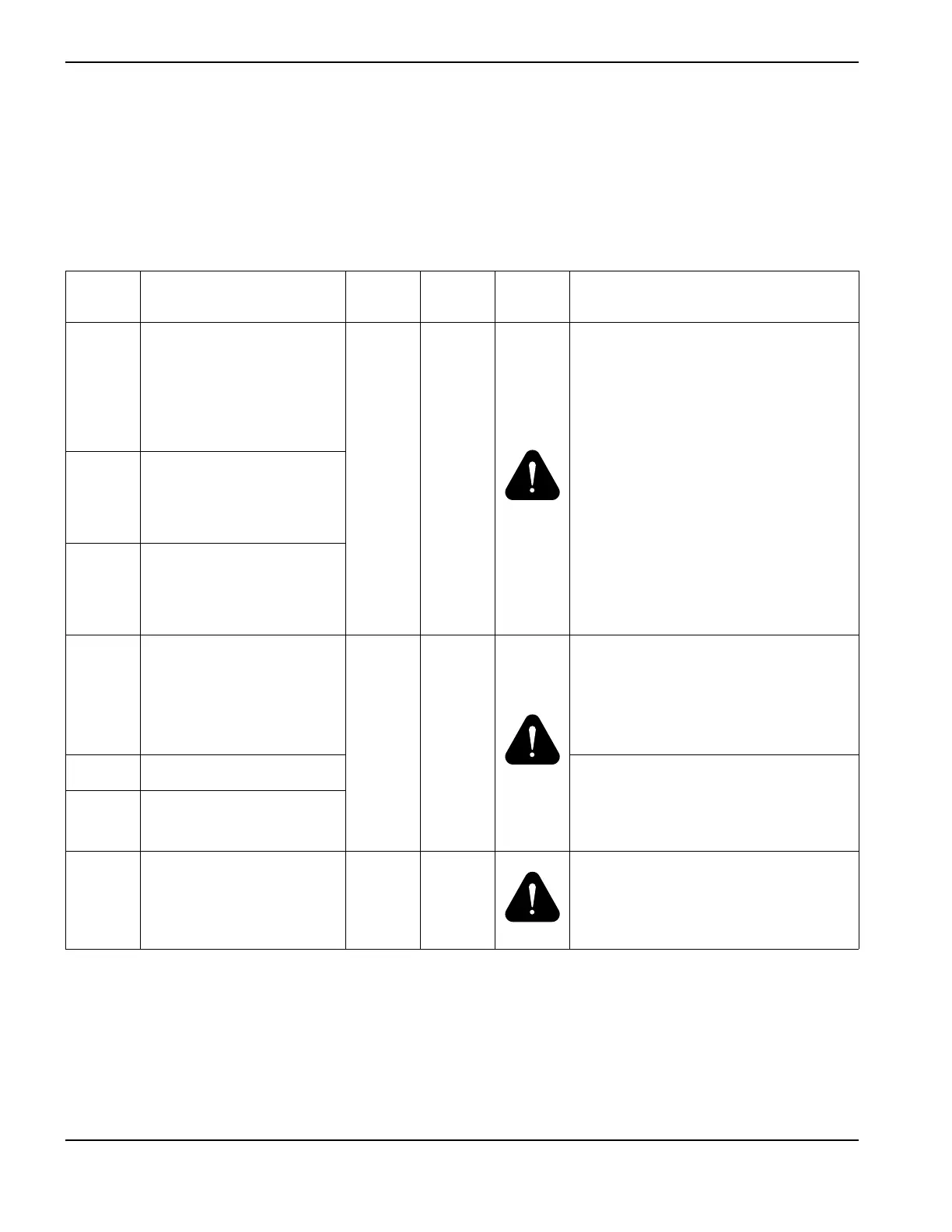
Fault
icon
Solutions
0-11-0 Remote controller cut mode
invalid. Valid remote cut
modes for Powermax125:
1–Normal; 2–CPA
(continuous pilot arc);
3 – gouge; 5 – lock.
On Off
There is a problem with the remote
controller or the software interface to the
system. The system cannot interpret the
cut mode, cut current, or pressure
information coming from the controller.
• Fix the controller.
• Check the interface cable.
0-11-1 Remote controller current
invalid. Valid remote current
settings for Powermax125
are: 30 – 125 A.
0-11-2 Remote controller pressure
invalid. Valid remote pressure
setting for Powermax125
depends on the torch.
0-12-1 Output gas pressure low
On Off
• Adjust the gas inlet pressure as
needed.
• Check for kinked or blocked air lines.
•Perform Test 10 – Pressure sensor on
page 163.
0-12-2 Output gas pressure high • The gas subsystem is not working
properly. Check the valve.
•Perform Test 10 – Pressure sensor on
page 163.
0-12-3 Output gas pressure
unstable
0-13-0 AC input unstable (line
resonance): Alert
Blinks
(3 Hz)
Off
• Perform a cold restart.
• If the fault does not clear, correct the
power source. Change the character,
generally the impedance, of the line.