EasyManuals Logo

Hypertherm Powermax 125 Service Manual

Hypertherm Powermax 125
317 pages
To Next Page IconTo Next Page
To Previous Page IconTo Previous Page
Page #150 background imageLoading...
Page #150 background image
150 Powermax125 Service Manual 808070
8 Troubleshooting and System Tests
Test 1 Voltage input
Symptom: Voltage fault (0-60-0, -1 or -2)
Check the line voltage at the top of the power switch (S1) with the switch in the OFF (O) position.
Check the input voltage to the input diode bridge with the switch in the ON (I) position.
The AC voltage between any 2 input wires should equal the line voltage.
If there is proper voltage to the power switch and low voltage to the input diode bridge, replace the power switch.
Check the output voltage of the input diode bridge.
Output VDC = Line Voltage x 1.414 VDC.
All values are ±15%.
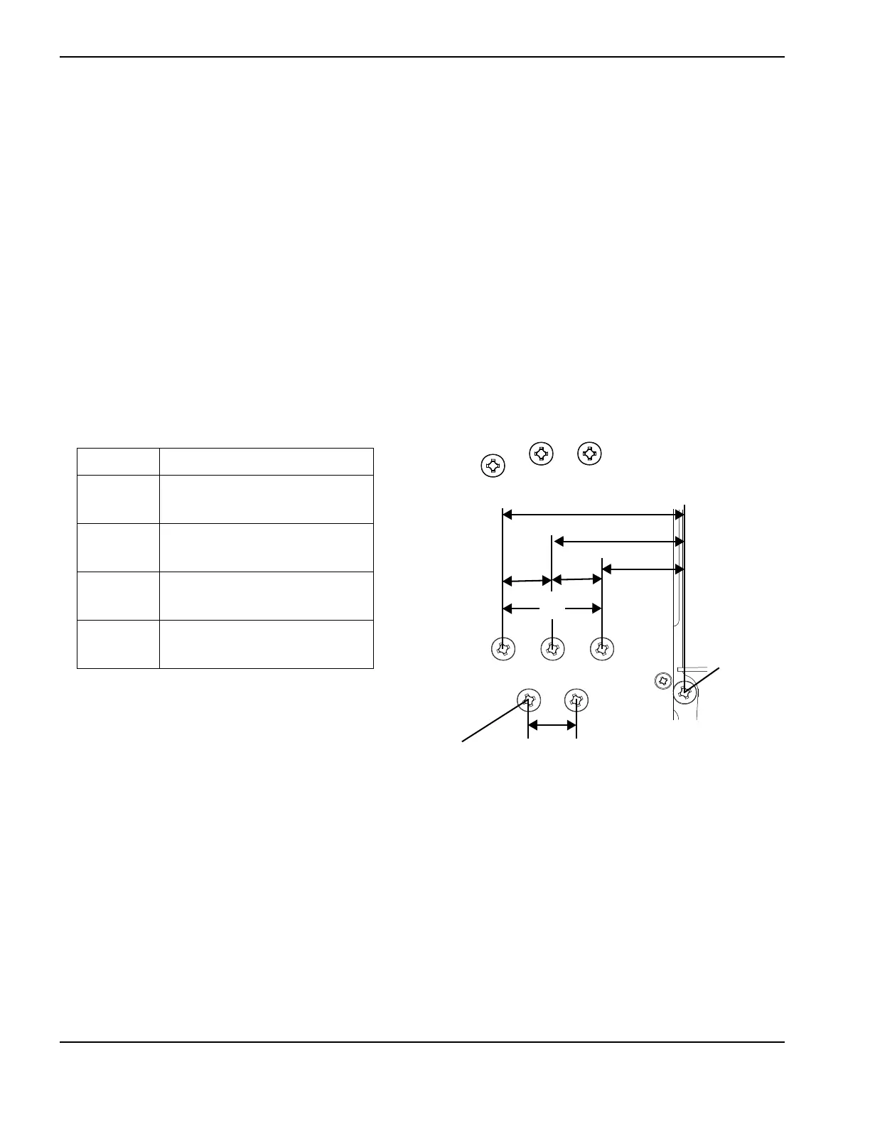
Figure 20
Wire colors may vary in power cords not purchased from Hypertherm.
3-phase
L1 Black (CSA)
Brown (CE)
L2 White (CSA)
Black (CE)
L3 Red (CSA)
Gray (CE)
PE Green (CSA)
Green/Yellow (CE)
LV
LV
LV
3 inputs to GRD LV/1.732LV
LV x 1 . 414Black wire
Ground
(GRD)
LV incoming line voltage

Table of Contents

Other manuals for Hypertherm Powermax 125

Questions and Answers:

Question and Answer IconNeed help?

Do you have a question about the Hypertherm Powermax 125 and is the answer not in the manual?

Hypertherm Powermax 125 Specifications

General IconGeneral
Output Current30-125 A
Input Power15.2 kW
Open Circuit Voltage300 VDC
Gas SupplyClean, dry, oil-free air or nitrogen
Input Power Cable Length10 ft (3 m)
Rated Output Current125 A
Gas TypeAir or nitrogen
Cutting Capacity1-1/4 inch (32 mm)
Pierce Capacity1 inch (25 mm)
Input Voltage200-600 V, 3-PH
Duty Cycle100% @ 125 A
CertificationsCSA
Maximum Clean Cut Thickness1-1/4 inch (32 mm)
Cooling MethodFan-cooled
Torch OptionsHand

Related product manuals