EasyManuals Logo

Hypertherm Powermax 125 Service Manual

Hypertherm Powermax 125
317 pages
To Next Page IconTo Next Page
To Previous Page IconTo Previous Page
Page #170 background imageLoading...
Page #170 background image
170 Powermax125 Service Manual 808070
9 Power Supply Component Replacement
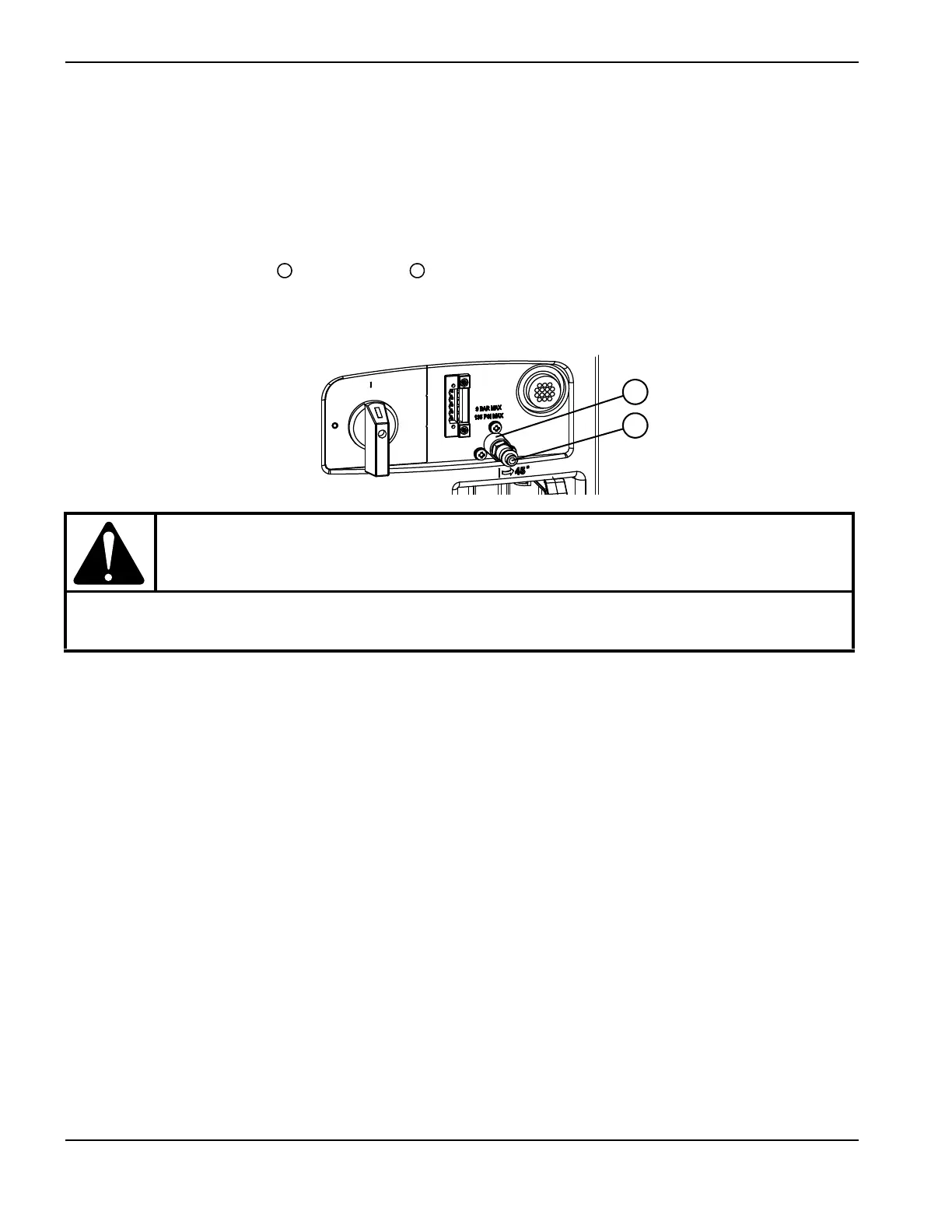
Installing the optional filter kit
1. Disconnect the power and gas supply. (See Disconnect the power and gas supply on page 166.)
2. Remove the gas inlet fitting from the bracket .
Figure 36
3. Apply thread sealant to the adapter fitting and tighten it into the bracket. (See Figure 37 on page 171.)
4. Apply thread sealant to the other side of the adapter fitting, and, with the arrow pointing toward the power supply,
tighten the filter onto the adapter fitting.
5. Apply thread sealant to the gas inlet fitting, and tighten it into the filter.
Kit number Description
228890 Kit: Eliminizer gas filter with protective metal cover for the Powermax105/125
CAUTION!
Never use PTFE tape on any joint preparation. Use only a liquid or paste thread sealant on male
threads.
1
2
1
2

Table of Contents

Other manuals for Hypertherm Powermax 125

Questions and Answers:

Question and Answer IconNeed help?

Do you have a question about the Hypertherm Powermax 125 and is the answer not in the manual?

Hypertherm Powermax 125 Specifications

General IconGeneral
Output Current30-125 A
Input Power15.2 kW
Open Circuit Voltage300 VDC
Gas SupplyClean, dry, oil-free air or nitrogen
Input Power Cable Length10 ft (3 m)
Rated Output Current125 A
Gas TypeAir or nitrogen
Cutting Capacity1-1/4 inch (32 mm)
Pierce Capacity1 inch (25 mm)
Input Voltage200-600 V, 3-PH
Duty Cycle100% @ 125 A
CertificationsCSA
Maximum Clean Cut Thickness1-1/4 inch (32 mm)
Cooling MethodFan-cooled
Torch OptionsHand

Related product manuals