Powermax125 Service Manual 808070 183
9 – Power Supply Component Replacement
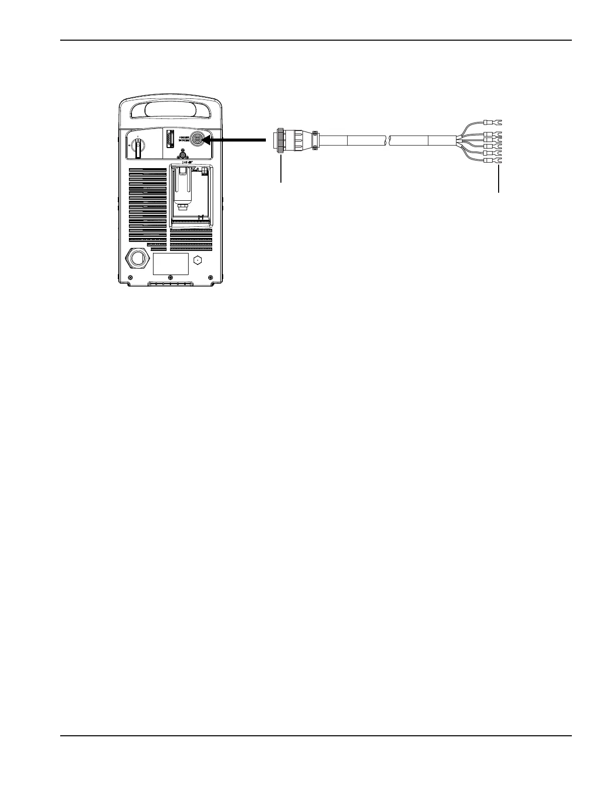
Figure 52
Installing the RS-485 serial interface cable
Refer to Connecting an optional RS-485 serial interface cable on page 104 for information on connecting an external
device to the RS-485 serial interface connector and for the part numbers of the RS-485 serial cables that Hypertherm
offers.
1. Complete the following procedures:
a. See Disconnect the power and gas supply on page 166.
b. See Remove the power supply cover on page 172.
c. See Remove the component barrier on page 173.
d. See Remove the end panel bracket on page 174.
2. Pry up the right edge of the power switch label using a knife or blade screwdriver. (See Figure 53.)
3. Peel the right half of the label back to the perforation.
4. Apply pressure to the left half of the label while tearing the right half away. Discard the right half of the label.
Kit number Description
228539 Kit: Serial interface port, internal cables, and RS-485 board